Introduction
I say, if your knees aren’t green by the end of the day, you ought to seriously re-examine your life. ~Bill Watterson, Calvin & Hobbes
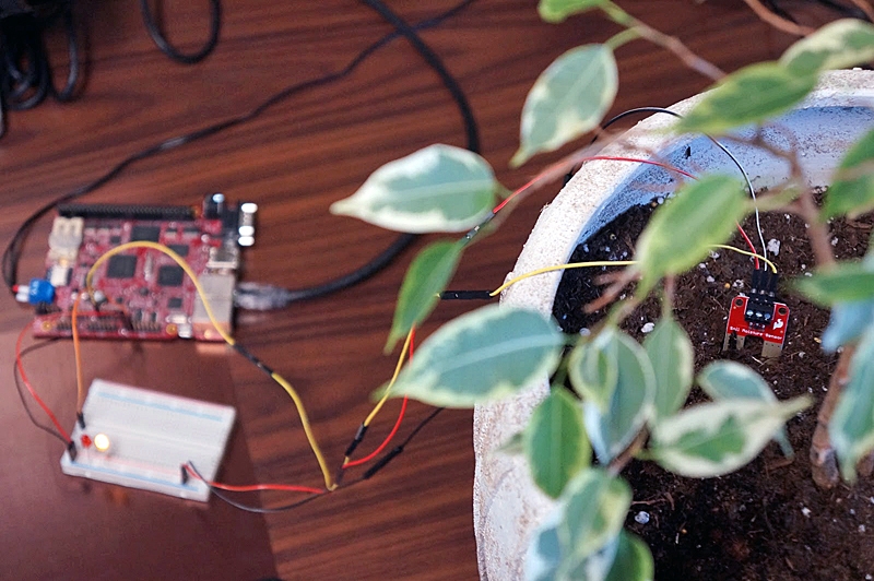
Green-thumbed techno junkies rejoice! For today, we’re going to take an introductory, prototype look at what it takes to digitally monitor the soil moisture content of a common houseplant so we know when to water it. We’re talking about using a single board computer to read from a soil moisture sensor from an Analog to Digital Convertor (ADC) and toggle an indicator LED using Digital Input and Output (DIO). Specifically, we’re going to be using a TS-7250-V2, but this guide can apply to many different boards.
Admittedly, the TS-7250-V2 is a bit overkill for the scope of this simple project, where a simple microcontroller would work, but it does provide us with a solid foundation for full-fledged autonomous garden projects. The TS-7250-V2 has five ADC channels, so you could hook it up to five different watering zones. It also has plenty of DIO pins for controlling and interfacing with external hardware, like turning on or off water pipes for example. Where things get really interesting is having the ability to run a web or API server from the Linux-powered board for access from anywhere in the world. So, there’s definitely room to grow here (pun intended). With that, let’s dig in.
Things We’ll Need
Here’s a list of the items we’ll be prototyping with today:
- TS-7250-V2 Single Board Computer
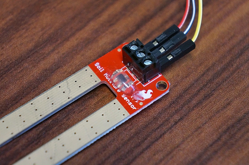
- SparkFun’s Soil Moisture Sensor
- 1x Red LED
- 1x Yellow LED
- 2x 330 Ω Resistors
- Breadboard
- Misc. Hookup Wires
Setting Up The Hardware
Where the rubber meets the road, or rather, where the sun meets the photosynthesizer. We’re going to hook up our components to the single board computer. For the soil moisture sensor, we need power, ground, and an ADC channel for the signal wire.
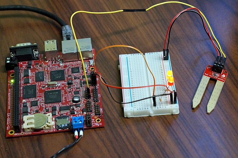
In order to prevent oxidation of the probes, we’re not going to apply constant power. Instead, we’re going to hook it up to a 3.3 VDC DIO pin so we can turn it on only when we’re ready to read what’s on the signal wire. We’ll call this our power enable pin. In order to visually see when power to the moisture sensor is active, we’re going to hook up a yellow LED to the DIO pin as well. Finally, we’re going to need some sort of indicator to let us know when the plant needs watering, so we’re going to hook up a red LED to another DIO pin. What we’re left with is something resembling the wiring diagram below.
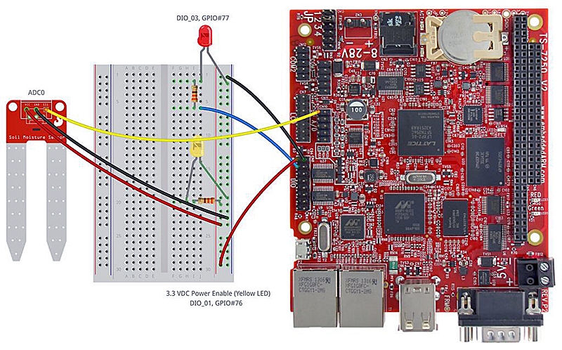
Notice, we’re connected to the DIO and A/D headers. The red LED is connected to DIO_03, or GPIO #77 in software. The power enable wire is connected to DIO_01, or GPIO #76 in software, which powers our moisture sensor and yellow LED. A ground pin for all of our components is conveniently located on DIO_01. After connecting everything, we can continue to software development, but before we do, let’s talk about protecting our sensor.
As we all know, electricity and water don’t get along, so before we go sticking our sensor into a moist environment, we should protect it. For indoor applications, simply using hot glue can provide good protection. For outdoor applications, hot glue won’t hold up to the sunshine and other elements very well, soconformal coatingwould be much better. Here, we’re working with an indoor houseplant, so hot glue was used, as seen in the image below.
Okay, let’s move onto the exciting software stuff!
Programming The Software
Tighten up your thinking cap; we’re going to unearth some C code. Now, this could very well be done in Python or another language, but we had someexample C codealready provided by Technologic Systems. Also, those coming from a microcontroller world might be more comfortable in implementing their hardware in C/C++, so we’ve shaped the ground to match that sort of landscape.
Start by taking a look at the code at theembeddedts/soil-watcher git repository. There are several files here including the example C code pulled directly from Technologic Systems calledevgpio.candevgpio.h. The evgpio library takes care of all the dirty details of dealing with the somewhat unique event driven GPIO of the TS-7250-V2. This is about the only thing specific to this example project. For other boards, you’ll need to utilize your own GPIO library. If your board happens to use the popularGPIO sysfs interface, you’re in luck because we have example code availablehere in Candhere in C++. Otherwise, refer to your board manual. With that said, let’s take a look at the main event —soil-watcher.c.
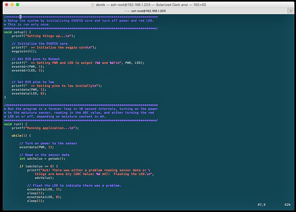
Essentially, what we’re looking at is a program that has a few functions, but primarily main(), setup() and run(). The setup() function sets everything up initially, preparing our system by turning off LEDs and initializing the GPIO pins. The run() function contains an infinite while loop that will continually monitor soil moisture readings and control the sensor power and red LED. The main() function simply parses command line parameters and calls setup() and run(). The other functions are mainly just helper functions. The code was heavily commented to make it easy to digest and understand so that we don’t have to dig into too many overwhelming details in this writeup.
Here’s what our program outputs as I leave it sit on my desk and then touch the two prongs together with my fingers:
Setting things up...
 >> Initialize the evgpio core
 >> Setting PWR and LED to output (76 and 77)
 >> Setting pins to low initially
Running application...

Ack! There was either a problem reading sensor data or things are bone dry (ADC Value: 8 mV)!  Flashing the LED.

Moisture content is OKAY (ADC Value: 1965 mV)!  Turning the LED off.
Moisture content is OKAY (ADC Value: 1977 mV)!  Turning the LED off.

Ack! There was either a problem reading sensor data or things are bone dry (ADC Value: 7 mV)!  Flashing the LED.

Moisture content is OKAY (ADC Value: 2186 mV)!  Turning the LED off.

Ack! There was either a problem reading sensor data or things are bone dry (ADC Value: 7 mV)!  Flashing the LED.
One of the finer points of our soil-watcher.c program is the (totally optional) ability to run as a daemon. This allows us to run the program in the background so-to-speak, although what’s actually happening is a little more complex. What we care about is that it frees up our shell as our program goes about its own way. We can see it running by using ps ax | grep soil-watcher.
This also redirects all output that the program would normally generate to /dev/null. So, no logging will be available using this method.
The next thing we’ll want to do with our program is make it start automatically when the system powers on. There are a few different ways of doing this, but the most popular is to add a init.d or systemd (example) script. For our TS-7250-V2, we’ll use init.d, as documented in the “Starting Automatically” section of the TS-7250-V2 manual. The file has already been created for you as soil-watcher.sh. To get it working on startup, follow these commands:
cp soil-watcher.sh /etc/init.d/soil-watcher

chmod +x /etc/init.d/soil-watcher

update-rc.d soil-watcher defaults

/etc/init.d/soil-watcher start
Then, when you reboot your system, our soil-watcher program should be running.
Closing Remarks
Now, the prototyping phase is over. If you’re satisfied with this mini-application, then you could start figuring out how to enclose the system and make it look like a finished product.
I would start by creating a false bottom in the planter in which to house the board and wiring. Then, I’d run some sort of flexible, thin conduit in which to run the wires for the LED and moisture sensor. A hole would be drilled in the planter and the red LED mounted in that hole, so it’s visible from the outside of the plant. Then, whenever I was walking by and seen the red LED, I would know it’s time to water the plant.
Really, this is just the tip of the iceberg. The principles taught in this tiny project of using DIO and ADC pins are applicable to many situations and projects. As mentioned earlier, using the TS-7250-V2 single board computer is massively overkill for this tiny project, but you now have a powerful and sturdy foundation on which to build so much more, which I hope you’ve felt inspired to do so.
If I were to take this further, I would want to build an automated garden with five different watering zones, hooked up to relays and solenoids to control water flow. I’d incorporate an online dashboard into the project by utilizing the Apache webserver and MySQL database to track and display historical data. With Node.js easily installable, I’d bring some IoT flare to the table by creating a REST API which I could use to monitor my soil in real time and open water valves with the push of a button on my phone.
Sources:
https://github.com/embeddedts/soil-watcher
https://wiki.embeddedTS.com/wiki/TS-7250-V2
https://files.embeddedTS.com/ts-arm-sbc/ts-7250-v2-linux/sources/