
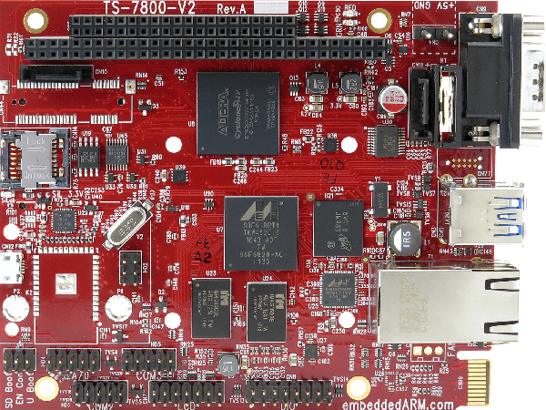
In this PWM crash course, we’ll be taking a look at what PWM is and how to use it by way of example. First, we’ll control the brightness of an LED and make it breathe, then we’ll control the position of a servo motor. This will all be done using the PWM channels on a TS-7800-V2.
Quick Intro to Pulse Width Modulation (PWM)
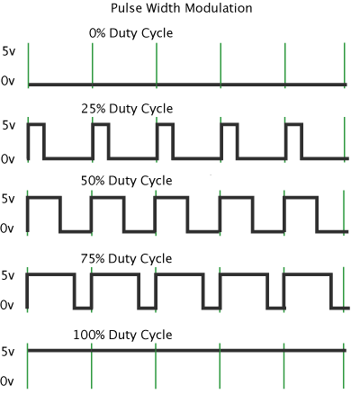
At its core, PWM is simply a way to get an analog-type signal from a digital source by quickly switching, or modulating, between on and off states. The amount of time that the signal is in the on state is called the pulse width. The full time between when the waveform starts and stops is called the period (green lines shown in figure above). The duty cycle is the “high time” within the period. The higher the pulse width, the higher the averaged output voltage will be. We can have a completely off state (0% duty cycle), a completely on state (100% duty cycle), and everything in between. These in between values are done by varying the pulse width, as visualized in the figure above.
For a more detailed and engineering explanation, take a look at the wikipedia article Pulse-width Modulation.
Installing PWM Control Utility ‘pwmctl’
Before we can jump into the examples, we need to download and install the pwmctl utility. This will make it really easy to take advantage of the PWM channels on the TS-7800-V2. All of the following commands should be ran on the TS-7800-V2.
First, we need to get connected to the internet. So, be sure you have an Ethernet cable connected and then issue the command to obtain an IP address:
dhclient
You should now be connected. You can test that you have an IP address by using ifconfig eth0. Once you’ve verified this, you’ll need to download the pwmctl.c source:
wget ftp://ftp.embeddedTS.com/ts-arm-sbc/ts-7800-v2-linux/samples/pwmctl.c
Finally, we’ll compile and install the utility:
gcc pwmctl.c -o pwmctl
mv pwmctl /usr/local/bin/
Perfect! You should now be able to check that it works by running pwmctl –help:
root@ts7800-v2:~# pwmctl --help
Usage: pwmctl [OPTION] ...

-c CHAN PWM Channel number 0..7
-d DUTYCYCLE Duty-cycle 0..4095 (or 0%..100%)
-g GEN Frequency generator 0 or 1

There are six PWM channels (0..5). These are presented on the
DIO header, pins 1,3,5,7,9,11).

The other channels (6 & 7) are actually the frequency-generators 0 and 1
respectively. For these, the DUTYCYCLE parameter is really the
number of period units, and the GEN parameter is really the selector
for the units. When GEN=0, the units are 1us, and when GEN=1, the units
are 100us. The period of the generator, then, is the number of period-
units multiplied by either 1 or 100
Now we’re ready for the examples! Be sure to keep the TS-7800-V2 manual handy, especially the PWM and DIO Header sections.
Making an LED Dim and Breathe
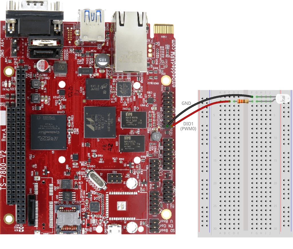
Perhaps the most basic demonstration of PWM is to dim an LED, so that’s where we’ll start. Grab an LED, a 330Ω resistor (or similar), some hookup wires, and a breadboard and get the LED connected as shown in the figure below:
Now that we’re hooked up, there’s an important note in the TS-7800-V2 PWM documentation which I’ll echo: “The DIO pins are active low, which means that a signal with, for example, a 20% duty-cycle will be low 20% of the time.”. This means, it’s slightly backwards from what you might think as what’s on and what’s off.
For full or 100% brightness, you issue the command:
pwmctl -c 0 -d 0% -g 0
For half or 50% brightness, use:
pwmctl -c 0 -d 50% -g 0
And to turn off the LED, use:
pwmctl -c 0 -d 100% -g 0
You can experiment with other values as well. Pretty soon, you’ll realize you can make very small steps from 0% to 100% brightness and then back down again to give the LED some life. This effect is called breathing. Let’s copy the pwmctl.c example code to pwmbreathe.c and modify the code to include an infinite loop to make the LED breathe like so:
   while(1) {

     for (int duty = 0; duty <= 4095; duty++) {
       reg = (1 << 29) | (chan << 21) | (gen << 20) | (duty << 8);

       printf("chan %d, gen %d, duty %d\n",
          (reg >> 21) & 7, (reg >> 20) & 1 , (reg >> 8) & 0xfff);

       syscon[0x4c / 4] = reg;

       usleep(300);
     }

     for (int duty = 4095; duty >= 0; duty--) {
       reg = (1 << 29) | (chan << 21) | (gen << 20) | (duty << 8);

       printf("chan %d, gen %d, duty %d\n",
          (reg >> 21) & 7, (reg >> 20) & 1 , (reg >> 8) & 0xfff);

       syscon[0x4c / 4] = reg;

       usleep(300);
     }

   }
Essentially, we’re just making very small steps from off to on and then back from on to off again. This is the effect we get (note: the eye doesn’t perceive the flickering that you see in the video captured):
[gfycat data_id="SarcasticFairDungbeetle"]You can now imagine using this dimming technique to control an RGB LED and get it to light up in different colors. Feel free to give that a whirl if you wish, but we’re going to move onto our next example of controlling a servo motor position.
Controlling a Servo Motor Position
For our final example, let’s take a look at how to control the position of a servo motor. We’ll be using this basic servo from Sparkfun. You’ll want to take a look at the datasheet for the servo you have. Essentially, to control the position, we’re going to vary the pulse width between two values as visualized in the figure below:
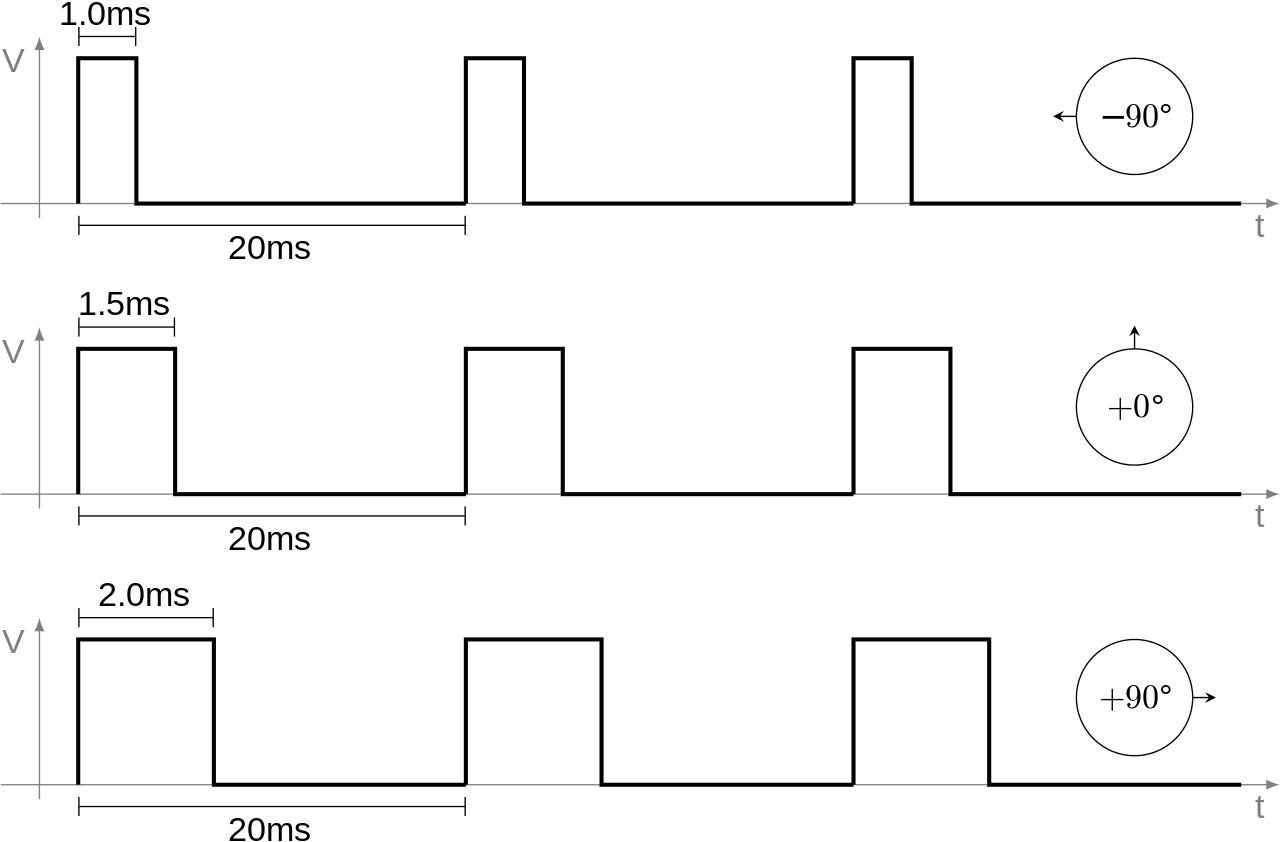
Effectively the servo isn’t really looking for a full-sweep PWM, instead it is looking for a variable pulse between 1 and 2 ms proportional to the desired servo position, and it wants this positional pulse delivered ata period of 20 ms.
Note that this figure is for visualization purposes and doesn’t accurately represent the duty cycles we’ll be using.
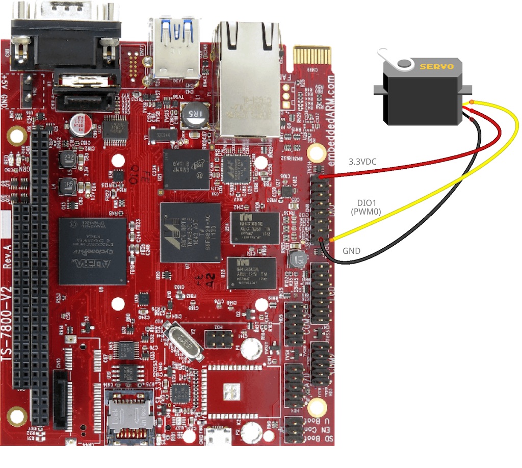
To get started, connect the servo motor to the TS-7800-V2 like shown in the figure below:
Once connected, we’re going to use the pwmctl utility to control the servo
For full right position, issue the command:
pwmctl -c 0 -d 3000 -g 0
For center position, use:
pwmctl -c 0 -d 3500 -g 0
For full left position, use:
pwmctl -c 0 -d 4000 -g 0
You can also use any values between 3000 and 4000 for fine control of the position. What you should see is something similar to the figure below:
[gfycat data_id="BronzeGranularGalago"]And there you have it! You can start to imagine writing some code to accept some inputs like a control knob or buttons to position the servo motor automatically. This comes in really handy with robotics and feedback systems.
Conclusion
That’s it for our PWM primer on the TS-7800-V2! We learned about what PWM is and how to use it in a couple of basic examples. Now it’s up to you to expand upon your new knowledge and incorporate it into your projects. Go build something amazing!
One thought on “PWM Primer with the TS-7800-V2”