Introduction
This guide aims to get you through the basic steps of getting your TS-7400-V2 up and running so you can begin development. It’s mostly an extrapolation of the official TS-7400-V2 Manual, but provides a more practical and casual approach in setting up connections, networking, and general environment.
Upgrading from the Original TS-7400
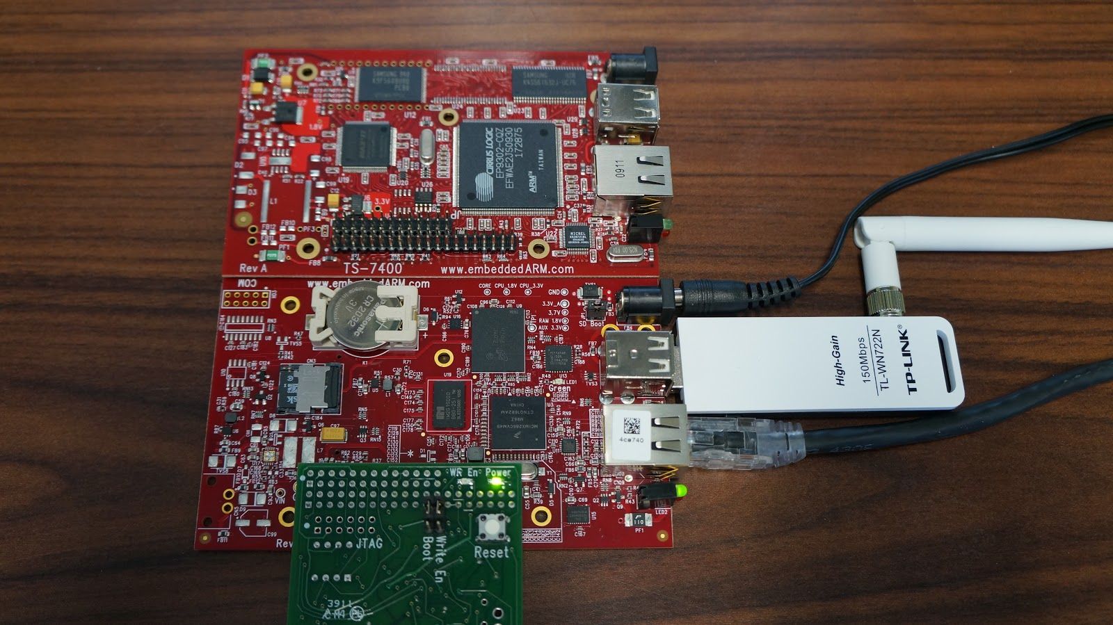
Yes, the “V2″ in TS-7400-V2 does stand for “version 2″, and it’s the upgrade path for users of the old TS-7400, which is pictured below for comparison. If you’re coming from the old TS-7400, you should find yourself comfortable with the TS-7400-V2 as we tried to keep things as similar as possible. You’ll still want to take a look at the “TS-7400-V2 Migration” section of the TS-7400-V2 manual for any pinout changes. Home
Connections
Let’s get our TS-7400-V2 hooked up! This includes our very basic connections we’ll need for most any development or project: power, serial console, Ethernet, and WiFi.
Jumpers
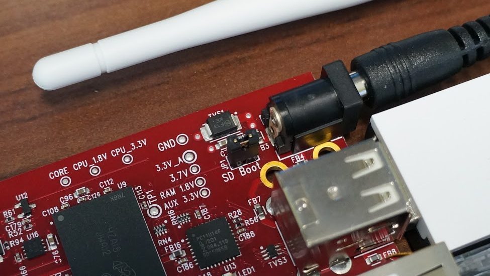
There isn’t much to be said for jumpers on the TS-7400-V2 other than to note there is a SD Boot jumper that determines whether or not the TS-7400-V2 will boot from the microSD card or the 2 GB onboard eMMC flash. For this guide, we’ll be booting to the microSD card. If we were further in our development, and ready for production deployment, we might think about loading our application to the eMMC flash and boot from it instead.
Serial Console
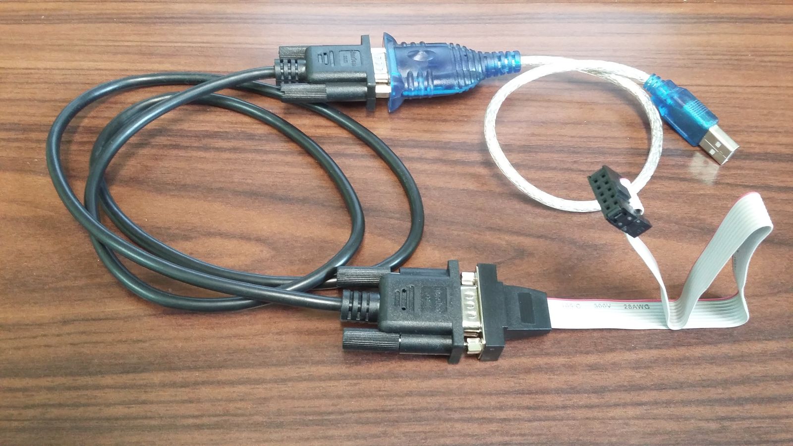
A good “˜ol serial console provides a reliable and consistent connection to the single board computer. Other methods like SSH or Telnet are nice too, but a serial console isn’t prone to failure because of botched startup scripts or network snafus. In order to get a serial console from the TS-7400-V2, we’ll need the following items: Home
- TS-9441 Peripheral Board
- DB9 to 10-Pin Header Adapter Cable (Part# RC-DB9)
- NULL Modem Cable (Part# CB7-05)
- Optional USB to Serial Adapter
These days, computers aren’t coming with a serial port, so the USB to serial adapter is handy to have. You can purchase them from computer stores or online, like this one from Amazon.com. We’ve had the best luck with those based on the Prolific PL2303 chipset, which has drivers for Windows and Mac easily available (Linux has these drivers pre-installed).
This is what you should have after connecting all of these adapters together:
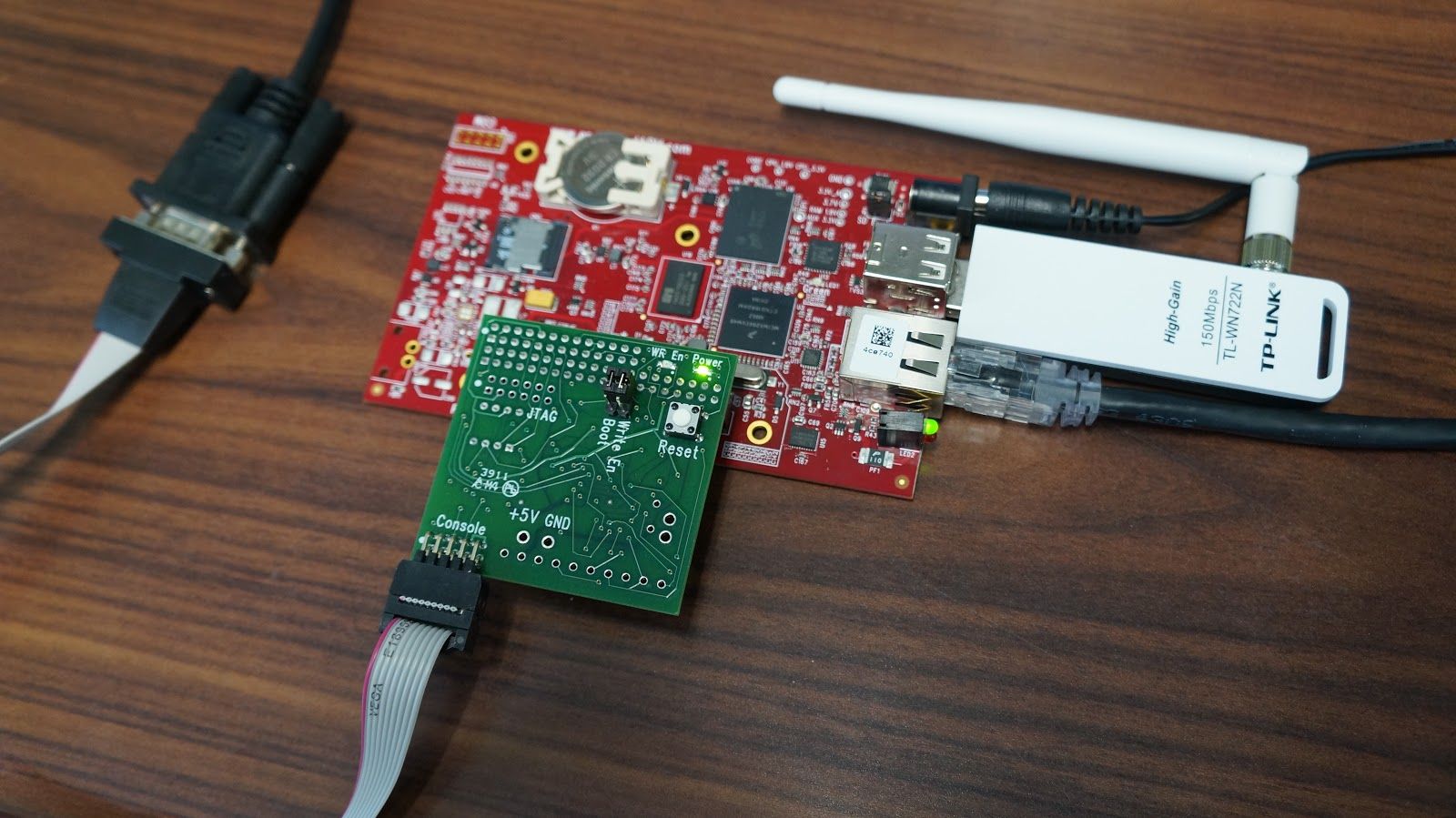
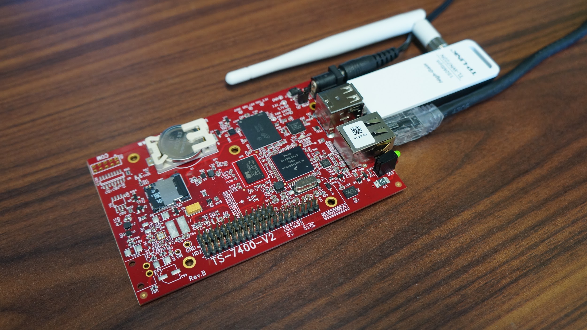
The final piece to this puzzle is the TS-9441 peripheral board, which we need because there isn’t an RS-232 transceiver onboard the TS-7400-V2. This is different from other single board computers, but it helps to reduce costs in the production stage when larger quantities are being ordered. The TS-9441 board can also assist with recovering a board in case something goes horribly wrong.
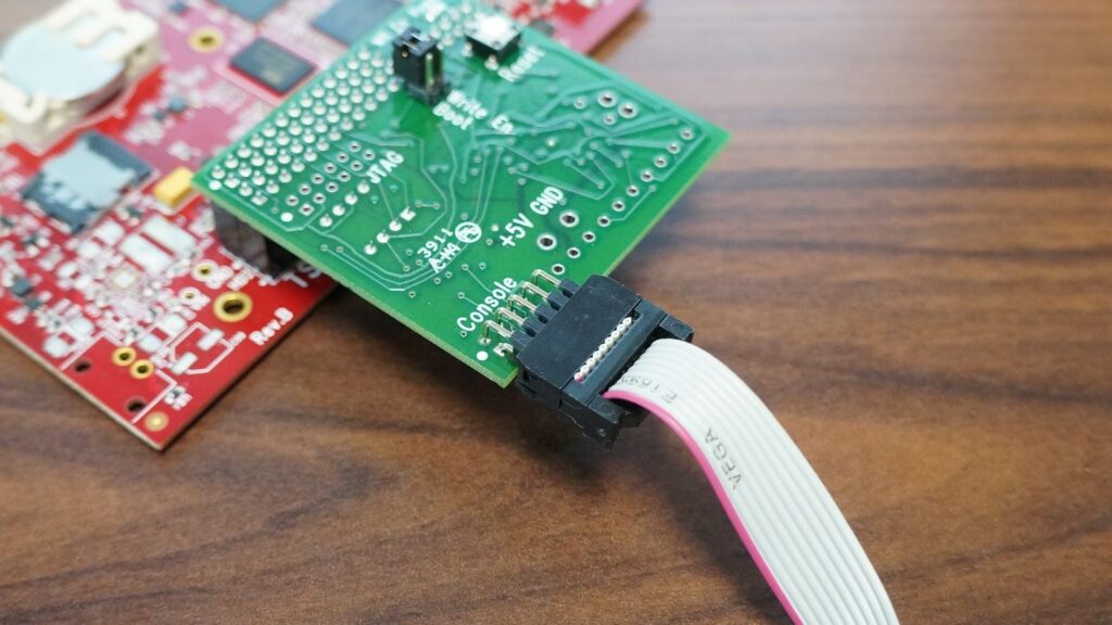
So, with the TS-9441 board in hand, it’s fairly obvious how it needs to connect with the TS-7400-V2 header pins. The console comes out on the 10-pin header of the TS-9441 labeled “Console”. Make sure that the red wire of the 10-Pin to DB9 adapter cable matches up with the white dot on the Console header, as shown in the picture above.
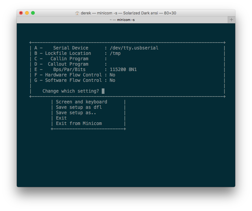
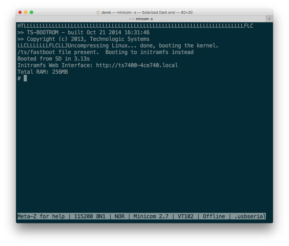
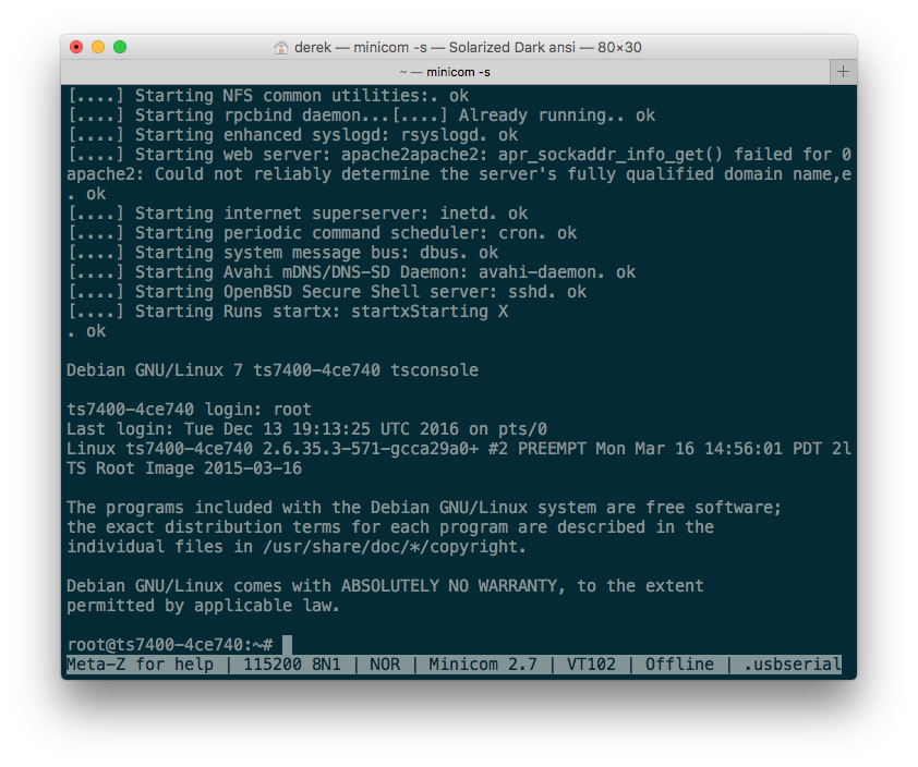
After installing drivers for your USB to serial adapter, plug the serial to USB adapter into your computer and follow the instructions given in the “Get a Console” section of the TS-7400-V2 manual. Since I’m developing from a Mac OSX machine, I’ll be using minicom, a command line program for terminal emulation. Linux users can also use minicom. Windows users will reach for PuTTY, a GUI terminal emulator. At any rate, after setting up your console and applying power, which we’ll talk about next, you’ll see something similar to the screenshot below (Mac OSX Terminal running minicom, using /dev/tty.usbserial):
Pro-tip: Running minicom alone will constrain the terminal row and column count to something pretty small that will never take up the whole terminal window. To take advantage of all the real estate your terminal window has to offer, run TERM=linux minicom instead. Remember to setup an alias as a shortcut for yourself!
Power
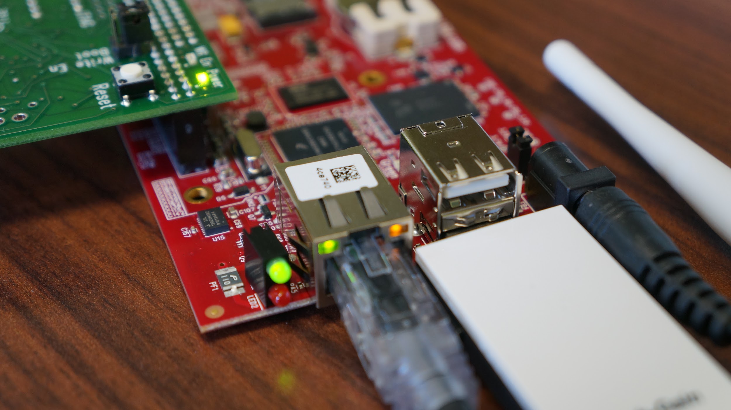
To power the TS-7400-V2 , we’ll be using the 5 VDC, 1.5 A power adapter (Part# PS-5VDC-REG-1AMP-BC) with barrel connector which we purchased when ordering the board. If you’re looking for other methods to power the board, please consult the “Booting up the Board” section of the TS-7400-V2 manual. The connector is located next to the USB ports on the TS-7400-V2. Simply plug it in, and you’ll be up and running. There will be a green status LED lit on the TS-7400-V2 and TS-9441 peripheral board. If you’ve been following along and completed the serial console steps, you should also see bootup messages.
Ethernet
Naturally, we’ll want to be able to connect this to the network so we can get it to talk with the local network or Internet, or even accessing the board via SSH or booting to an NFS filesystem. There is only one Ethernet port on the TS-7400-V2 designated as eth0, which is next to the USB ports. So, plug in a standard Ethernet cable connected to your router, and we should be good to proceed to the next steps! Home
Pro Tip: If you’d like to see all of the network interfaces, simply execute the command “˜ifconfig -a’ to see all available interfaces, and “˜ifconfig’ to see all enabled interfaces.
USB Wireless Adapter (Optional)
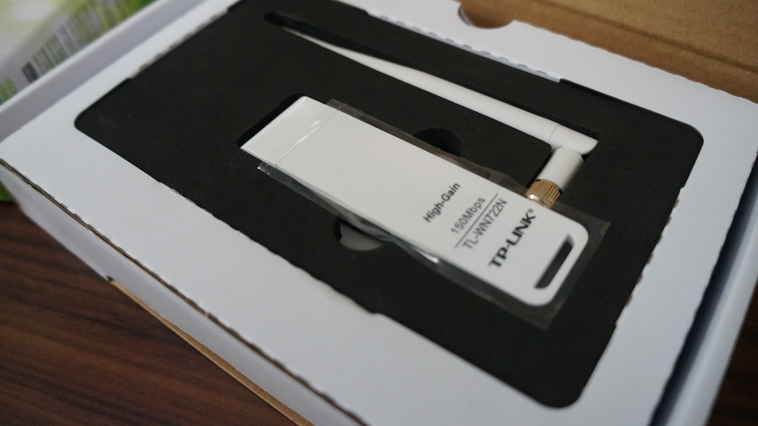
The TS-7400-V2 can be ordered with an optional USB wireless adapter. As of this writing, it’s the TP-LINK TL-WN722N, which uses the Atheros AR9002U chipset. Simply take the cap off and plug it into one of the two USB ports. Once the wireless interface is enabled, which we’ll talk about soon, you’ll see a green status LED light up.
About the Embedded Linux Environments
There are two sources from which to boot on the TS-7400-V2: the onboard 2 GB eMMC flash and microSD card (sold as a separate option, included in development kit). Each of these boot sources, or boot drives, contain two Linux environments: 1.) fastboot, which boots to a minimalistic initial ramdisk using busybox shell in about 3 seconds, and 2.) a full Debian distribution, which is more familiar to most Linux users, which boots in about 45 seconds. More on both of these in the next section. We’ll be working in the Debian environment for this guide.
Pro Tip: For development, best practice is to boot to microSD card for ease of recovery should something go wrong. Just plug the microSD card into a Linux development machine and modify files directly.
Furthermore, there are some helpful user space utilities preloaded with the TS-7400-V2 which make it easy to do things like toggle DIO and LEDs called tshwctl (TS Hardware Control). A quick look at the –help menu gives you an idea of what it’s capable of:
root@ts7400-4ce740:~# tshwctl --help
Usage: tshwctl [OPTION] ...
Technologic Systems TS-76xx/TS-46xx/TS-74xx manipulation.

General options:
  -g, --getmac            Display ethernet MAC address
  -s, --setmac=MAC        Set ethernet MAC address
  -R, --reboot            Reboot the board
  -t, --getrtc            Set system time from RTC
  -S, --setrtc            Set RTC time from system
  -o, --rtcinfo           Print RTC info, batt, temp, etc.
  -v, --nvram             Get/Set RTC NVRAM
  -i, --info              Display board info
  -e, --greenledon        Turn green LED on
  -b, --greenledoff       Turn green LED off
  -c, --redledon          Turn red LED on
  -d, --redledoff         Turn red LED off
  -X, --resetswitchon     Enable reset switch
  -Y, --resetswitchoff    Disable reset switch
  -D, --setdio=<pin>      Sets DDR and sets specified pin(s)
  -O, --clrdio=<pin>      Sets DDR and clears specified pin(s)
  -G, --getdio=<pin>      Clears DDR and gets DIO pin(s) input value
  -W, --watchdog          Daemonize and set up /dev/watchdog
  -q, --cputemp           Print CPU internal and external temperature
  -h, --help              This help
  -M, --timewkup=<time>   Time in seconds to wake up after
  -m, --resetswitchwkup   Wake up at reset switch is press
  -F, --standby           Standby CPU, must specify -M|-m to wkup
  -L, --sleep             Sleep CPU, must specify -M|-m to wkup
  -N, --canon             Enable CAN transcievers
  -f, --canoff            Disable CAN transcievers
  -V, --cpuadc            Read and print CPU LRADC values
For example, issuing the command tshwctl –redledon will turn on the red LED next to the Ethernet port. Home
Default Boot to Debian
At this point, we should be looking at a shell terminal, awaiting our commands. This shell is what we call an initial RAM disk, or initrd, with a Busybox shell. It’s a minimalistic, read-only environment which can be booted quickly (3.13 seconds) and begin executing your programs. Busybox is known as the “The Swiss Army Knife of Embedded Linux”, and you can accomplish quite a bit here. This is an excellent spot to put production-ready code because of the fast bootup and the read-only nature. For development, the Debian environment, which is pre-installed on the startup drive, is perhaps the easiest to work with, especially for those getting their feet wet in embedded Linux. So, we’re going to boot to the Debian environment, which gives us access to not only a more familiar Linux environment with tools like apt-get and compilers, but also an environment with more storage and debugging tools. We could type the command exit to begin booting to Debian, but we don’t want to do this every time. Instead, we’ll simply remove the file /ts/fastboot to boot to Debian by default as documented in the “Initramfs” section of the TS-7400-V2 manual. You should now see Debian startup sequence, followed by a login. For this, we’re just going to use “˜root’ as the user name. There is no password by default.
Pro Tip: If you’d like to use SSH after setting up your network connection, you’ll need to set a password. Run passwd to create a password followed by dpkg-reconfigure openssh-server. Also, refer to the “Setting up SSH” section of the TS-7400-V2 manual.
Pro Tip: If you’d like to run your application automatically upon boot, which is a very common request, take a look at the “Starting Automatically” section of the TS-7400-V2 manual.
Setup Networking
Next, let’s take a look at getting connected to the network and Internet through wired and wireless connections.
Wired
If you recall, we’re going to be setting up our eth1 network interface. For this, we’re going to follow the “Configuring the Network” section of the manual. First, we’ll enable the network interface, and then we’ll go about obtaining an IP address. The easiest way to get an IP address is dynamically using DHCP. For some applications, like a web server, a static IP address is better to use. We’ll take a look at both.
Dynamic IP
First, we need to enable the eth0 network interface by issuing the following command:
root@ts7400-4ce740:~# ifconfig eth0 up
root@ts7400-4ce740:~#
Then, in order to get an IP address, we issue the command:
root@ts7400-4ce740:~# dhclient eth0
RTNETLINK answers: File exists
root@ts7400-4ce740:~#
Issuing the ifconfig command should show us our connection information, which in this case the board was assigned the IP address of 192.168.1.135:
root@ts7400-4ce740:~# ifconfig
eth0      Link encap:Ethernet  HWaddr 00:d0:69:4c:e7:40
          inet addr:192.168.1.135  Bcast:192.168.1.255  Mask:255.255.255.0
          UP BROADCAST RUNNING MULTICAST  MTU:1500  Metric:1
          RX packets:21 errors:1 dropped:0 overruns:0 frame:1
          TX packets:17 errors:0 dropped:0 overruns:0 carrier:0
          collisions:0 txqueuelen:1000
          RX bytes:6272 (6.1 KiB)  TX bytes:3408 (3.3 KiB)
          Base address:0x8000

lo        Link encap:Local Loopback
          inet addr:127.0.0.1  Mask:255.0.0.0
          UP LOOPBACK RUNNING  MTU:16436  Metric:1
          RX packets:820 errors:0 dropped:0 overruns:0 frame:0
          TX packets:820 errors:0 dropped:0 overruns:0 carrier:0
          collisions:0 txqueuelen:0
          RX bytes:52429 (51.2 KiB)  TX bytes:52429 (51.2 KiB)

root@ts7400-4ce740:~#
Nothing to it! You should now be able to ping an external URL to test your connection:
root@ts7400-4ce740:~# ping debian.org
PING debian.org (140.211.15.34) 56(84) bytes of data.
64 bytes from busoni.debian.org (140.211.15.34): icmp_req=1 ttl=57 time=26.8 ms
64 bytes from busoni.debian.org (140.211.15.34): icmp_req=2 ttl=57 time=31.9 ms
64 bytes from busoni.debian.org (140.211.15.34): icmp_req=3 ttl=57 time=25.6 ms
64 bytes from busoni.debian.org (140.211.15.34): icmp_req=4 ttl=57 time=26.1 ms
^C
--- debian.org ping statistics ---
4 packets transmitted, 4 received, 0% packet loss, time 3003ms
rtt min/avg/max/mdev = 25.657/27.640/31.936/2.518 ms
root@ts7400-4ce740:~#
Static IP
For this, we’ll edit the /etc/network/interfaces file to read like the following. The highlighted section is what we’re adding. Make sure to modify it to fit your specific network settings. Home
# Used by ifup(8) and ifdown(8). See the interfaces(5) manpage or
# /usr/share/doc/ifupdown/examples for more information.

# We always want the loopback interface.
#
auto lo
iface lo inet loopback

auto eth0
iface eth0 inet static
  address 192.168.1.120
  netmask 255.255.255.0
  gateway 192.168.1.1
The next thing we need is to tell our network interface which DNS nameservers to use, so that we can ping by domain name, like debian.com. For this, we’ll edit /etc/resolv.conf and use the same gateway IP from above as the nameserver. You file should look like something like this:
root@ts7400-4ce740:/var/www# cat /etc/resolv.conf
nameserver 192.168.1.1
After saving your changes, we simply need to enable the interface and then reload the service responsible for the network interfaces. To do this, we run the commands:
root@ts7400-4ce740:~# ifconfig eth0 up
root@ts7400-4ce740:~# service networking stop
root@ts7400-4ce740:~# service networking start
Then, you should be able to run ifconfig eth0 and see the settings applied.
root@ts7400-4ce740:~# ifconfig eth0
eth0      Link encap:Ethernet  HWaddr 00:d0:69:49:6b:63
          inet addr:192.168.1.120  Bcast:192.168.1.255  Mask:255.255.255.0
          inet6 addr: fe80::2d0:69ff:fe49:6b63/64 Scope:Link
          UP BROADCAST RUNNING MULTICAST  MTU:1500  Metric:1
          RX packets:450 errors:0 dropped:0 overruns:0 frame:0
          TX packets:38 errors:0 dropped:0 overruns:0 carrier:0
          collisions:0 txqueuelen:0
          RX bytes:78249 (76.4 KiB)  TX bytes:6932 (6.7 KiB)

root@ts7400-4ce740:~#
You may want to test your connection at this point. Try pinging your gateway, aka router. You’ll know it’s successfully up and running when you see 0% packet loss in the report.
root@ts7400-4ce740:~# ping 192.168.1.1
PING 192.168.1.1 (192.168.1.1) 56(84) bytes of data.
64 bytes from 192.168.1.1: icmp_req=1 ttl=64 time=2.74 ms
64 bytes from 192.168.1.1: icmp_req=2 ttl=64 time=2.94 ms
64 bytes from 192.168.1.1: icmp_req=3 ttl=64 time=3.58 ms
64 bytes from 192.168.1.1: icmp_req=4 ttl=64 time=3.95 ms
^C
--- 192.168.1.1 ping statistics ---
4 packets transmitted, 4 received, 0% packet loss, time 3002ms
rtt min/avg/max/mdev = 2.740/3.304/3.951/0.490 ms
root@ts7400-4ce740:~#
Wireless
The USB wireless dongle sold with the TS-7400-V2, the TP-LINK TL-WN722N, uses the Atheros ath9k_htc driver and is not only capable of connecting to a wireless access point, but it can also behave as an access point itself (aka master mode). We’ll concentrate on connecting to an access point in this guide. If you’d like to use it as an access point, you’ll want to review the “Host a WIFI Access Point” section of the TS-7400-V2 manual.
Since we’ve already completed the step of creating the interface configuration file in the wired section before this, we’ll just jump right into enabling the interface, scanning for an access point, and then associating with it.
Enabling the wireless interface is a simple command: Home
ifconfig wlan0 up
Then, we’ll want to scan for access points using iwlist like so:
iwlist wlan0 scan
The output can be overwhelming, so you may want to filter out just the essid names using the command:
iwlist wlan0 scan | grep ESSID | cut -d':' -f2
Okay, so once you’ve identified an access point you want to connect to, you’ll need to associate with it. Now, there are open access points that don’t require any credentials to associate and there are protected ones using WEP or WPA security types.
Connecting to an Open Network
This is the easiest. You’ll be able to simply issue the following command to associate:
iwconfig wlan0 essid "default"
Now, make sure you’ve associated with the access point:
root@ts7400-4ce740:~# iwconfig wlan0
wlan0     IEEE 802.11bgn  ESSID:"default"
          Mode:Managed  Frequency:2.417 GHz  Access Point: c0:ff:ee:c0:ff:ee
          Bit Rate=1 Mb/s   Tx-Power=20 dBm
          Retry  long limit:7   RTS thr:off   Fragment thr:off
          Encryption key:off
          Power Management:off
          Link Quality=70/70  Signal level=-34 dBm
          Rx invalid nwid:0  Rx invalid crypt:0  Rx invalid frag:0
          Tx excessive retries:0  Invalid misc:0   Missed beacon:0
Finally, run udhcpc -i eth0 to get an IP address.
Connecting to a WEP Protected Access Point
Very similar to “˜Open Access Point’ section above except you’ll need to specify a password:
iwconfig wlan0 essid "default" key "yourpassword"
Same as above, follow up with iwconfig wlan0 and udhcpc -i wlan0.
Connecting to a WPA Protected Access Point
For this, we’re going to use the wpa_passphrase and wpa_supplicant utilities which make life easier. First, create the /etc/wpa_supplicant/ directory and generate a passphrase configuration file. Replace “˜the_essid’ and “˜the_password’ with the essid and password to connect to the access point.
mkdir /etc/wpa_supplicant/
wpa_passphrase the_essid the_password >> /etc/wpa_supplicant/wpa_supplicant-wlan0.conf
You can take a look at this file, but essentially it contains information and a hashed password for the association. Next step is to start the wpa_supplicant daemon which will run in the background.
wpa_supplicant -iwlan0 -c/etc/wpa_supplicant/wpa_supplicant-wlan0.conf -B
You should see output similar to this: Home
root@ts7400-4ce740:~# wpa_supplicant -iwlan0 -c/etc/wpa_supplicant.conf -B
 Successfully initialized wpa_supplicant
 root@ts-imx6:~# [  306.924691] wlan0: authenticate with 28:cf:da:b0:f5:bb
 [  306.959415] wlan0: send auth to 28:cf:da:b0:f5:bb (try 1/3)
 [  306.968137] wlan0: authenticated
 [  306.978477] wlan0: associate with 28:cf:da:b0:f5:bb (try 1/3)
 [  306.988577] wlan0: RX AssocResp from 28:cf:da:b0:f5:bb (capab=0x1431 status=0 aid=9)
 [  307.009751] wlan0: associated
 [  307.012768] IPv6: ADDRCONF(NETDEV_CHANGE): wlan0: link becomes ready
 [  307.047989] wlcore: Association completed.
Then, same as the other sections above, follow up with iwconfig wlan0 and udhcpc -i wlan0.
Finally, if you want your connection to be there when you reboot, you’ll need to configure systemctl to automatically set everything for you.
systemctl enable wpa_supplicant@wlan0
systemctl start wpa_supplicant@wlan0
As always, feel free to review the “WIFI Client” section of the TS-7400-V2 manual for more information.
Conclusion
In this getting started guide, we took a quick look at how to get everything connected, how to communicate with the board, and how to setup networking. You should be well on your way in developing your application. Once you’ve finished with development and are ready to move into production, you can take the TS-9441 peripheral board off and replace it with your own peripheral board. Also, be sure to take a look at the available rugged enclosure to protect your system. Home
Is there anything else you’d like to see added to this practical getting started guide for the TS-7400-V2? Be sure to comment below, and we’ll get it added!