![]()
BACnet is a data communication protocol for Building Automation and Control Networks. Developed by the American Society of Heating, Refrigerating and Air-Conditioning Engineers (ASHRAE), BACnet is a national standard in more than 30 countries around the world, and an ISO global standard. It was created to have a unified communication system for different devices across different manufacturers. Manufacturers of BACnet devices create a wide range of monitor and control modules, from basic IO, to analog, to specialized devices such as gas monitors. Home
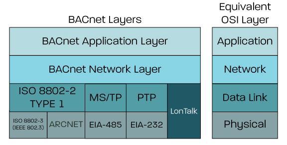
BACnet itself is a protocol definition that covers the Application, Network, Data Link, and Physical layers. Numerous Data Link and Physical layer definitions exist for BACnet, however the most common are BACnet MS/TP (Token over RS-485), and BACnet/IP (or BACnet/IPv6).
Technologic Systems’ TS-7680 was designed with BACnet support in mind. Including 24 V AC or DC operation, multiple Ethernet ports, and multiple RS-485 ports; one of the RS-485 ports is able to control and supply power to downstream peripherals.
 To demonstrate the BACnet compatibility of the TS-7680 we have created a simple demo application that integrates BACnetMS/TP, BACnet/IP, and the previously mentioned power control. The BACnet software layer is provided by BACnet stack (http://bacnet.sourceforge.net/), which is a set of open source and free tools to integrate with BACnet devices. Initial setup and testing of BACnet stack software with MS/TP and IP devices on the TS-7680 can be found on our website: https://wiki.embeddedTS.com/wiki/TS-7680_BACnet
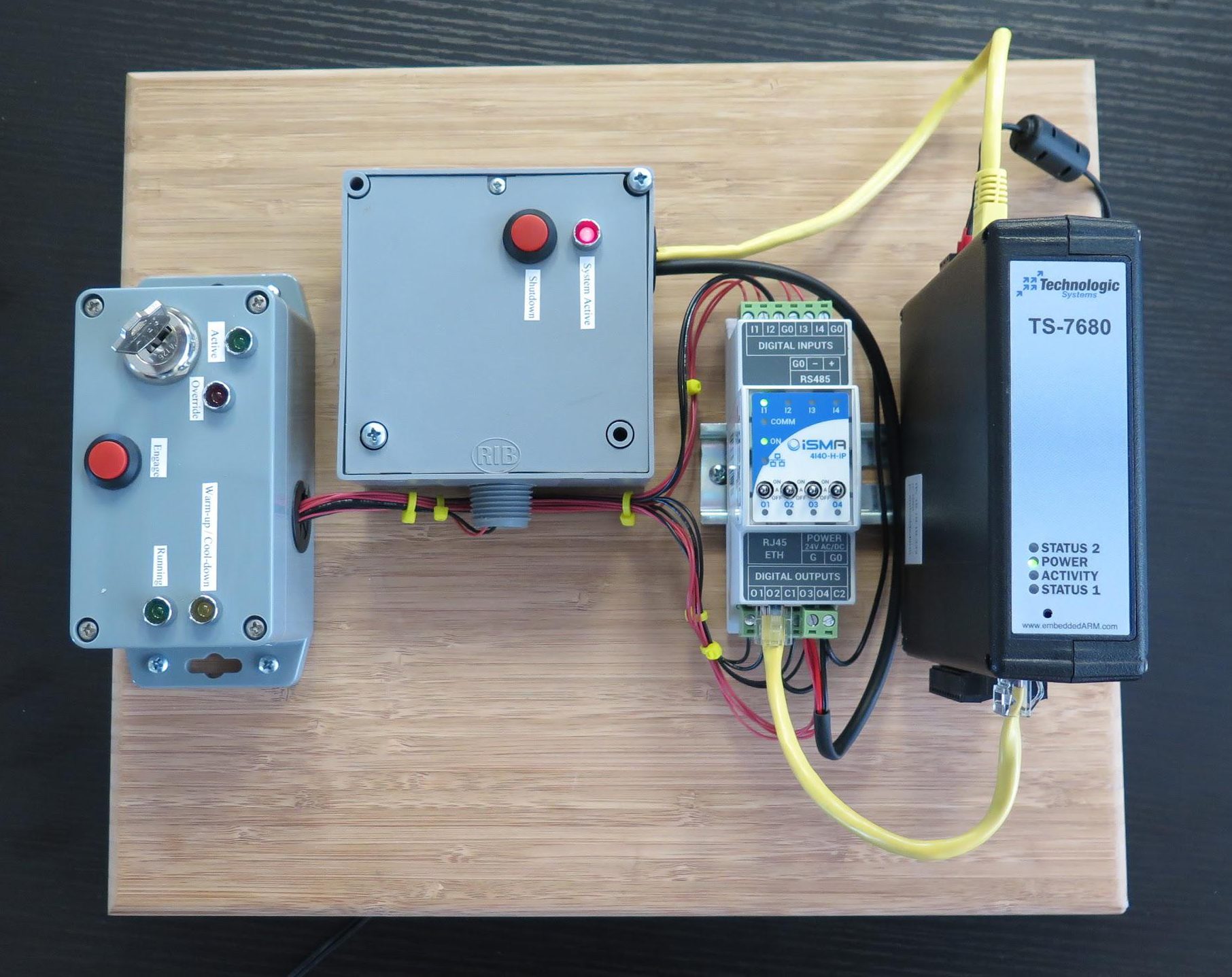
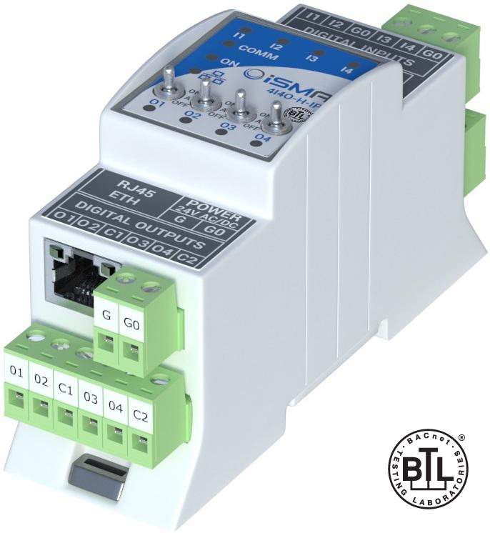
The finalized demo includes a TS-7680-128-4GF-I as the main device, an iSMA-B-4I4O-H-IP I/O module for BACnet/IP, and an RIBTW2401B-BC I/O module for BACnetMS/TP. The iSMA device contains four dry-contact inputs and four relay outputs. The RIB device contains a single dry contact input and a single relay output. The TS-7680 and the iSMA device are both mounted on a small section of DIN rail, while the RIB device and control box are directly screwed into the display panel.
Operation
There are three main software components to the whole demo. When power is applied to the TS-7680, it begins booting to Debian. During the bootup process, power is enabled on the RS-485 port, which powers the two BACnet modules. Additionally, the RS-485 bus is set up, and a separate daemon is run to monitor the push switch on the TS-7680. This push switch can be used to initiate a safe reboot of the whole system. At this time, the BACnet/IP and BACnetMS/TP applications are both started. These two applications are tools we have written using the BACnet stack software. They are separated out for a less complicated operation, meaning, ultimately, both applications have very simple logic. Once the System Active LED turns on, then all of the software and hardware have been fully initialized.
The BACnetMS/TP application is the simpler of the two, acting as supervisory IO. The System Active LED is turned on via a BACnetMS/TP operation at startup and is left on until late in the TS-7680 shutdown/reboot cycle. The Shutdown button is monitored by the BACnetMS/TP application. If it is held down for about 2 seconds, the BACnetMS/TP application will begin a safe shutdown of the TS-7680. Once the System Active LED turns off BACnet is no longer active and power can be removed after about 10 seconds to ensure the TS-7680 has fully shut down. The Shutdown button, however, has its contacts routed through the keyswitch also present on the demo. This provides a full hardware lockout to ensure that the system cannot be shut down while the rest of the controls are in operation. Home
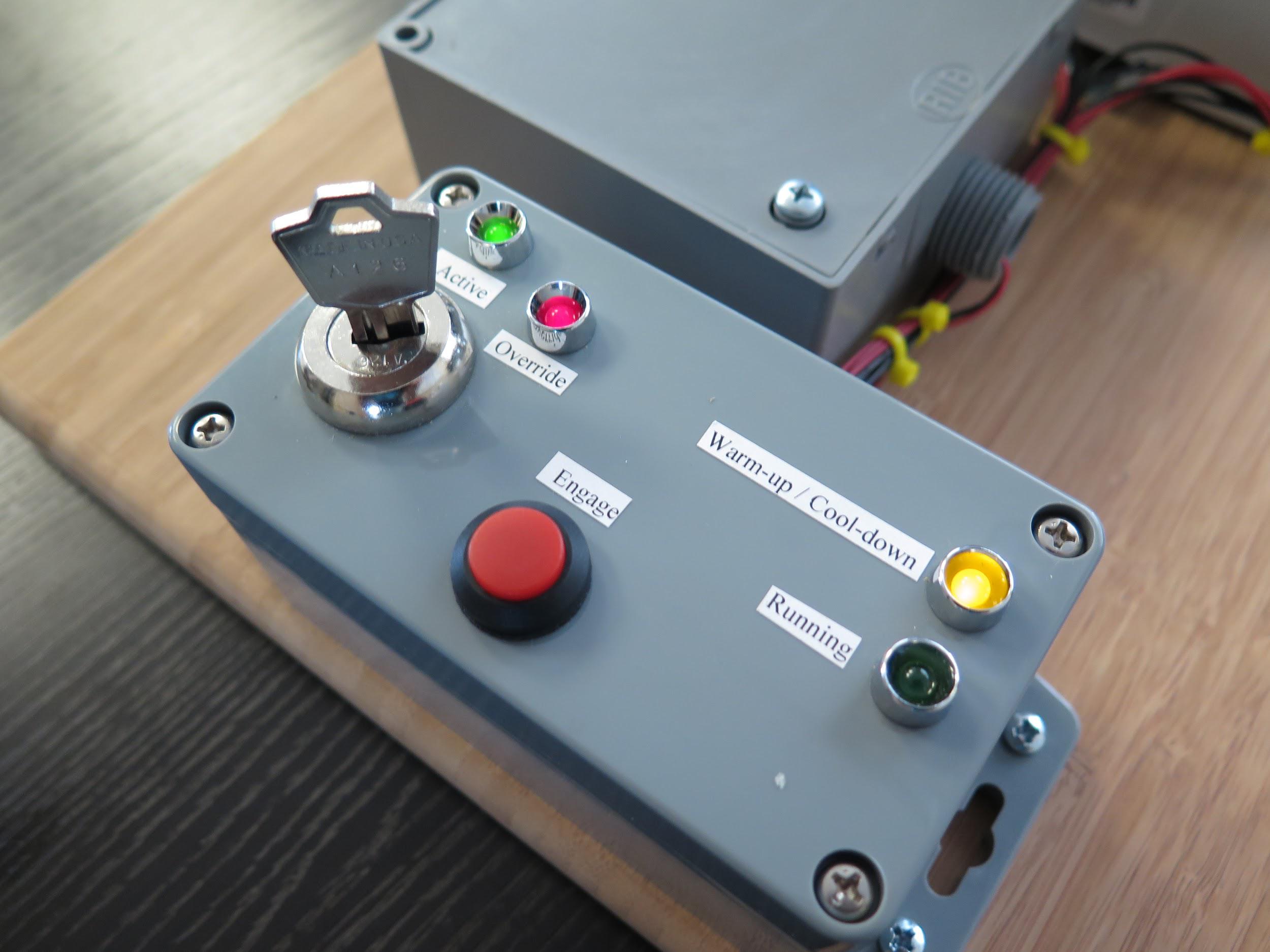
Before going into the BACnet/IP application, let’s take a moment to discuss the purpose of the demo. The control box presents a number of I/O: a keyswitch, a button, and some LEDs. The behavior of the application is intended to mimic a system which requires a warm-up and cool-down period in addition to a run time. This behavior was not modeled after any particular control scheme and was developed to simply show software flexibility. Any mention of “device” below does not refer to a physical device and only refers to this emulated “device” controlled by the BACnet/IP application that has different states and requires specific operational parameters.
The BACnet/IP application is more complex than the supervisory I/O. In addition to BACnet communication processing, it also contains a state machine that handles each stage of the “device’s” operation. The BACnet/IP application will monitor all four inputs (the three keyswitch positions and the Engage button), and set outputs (the four LEDs) based on a state machine laid out in the application. This portion of the demo is completely under software control.
The main focal point of the control box is the keyswitch. It is a three position keyswitch, with Disabled, Active, and Override positions. The keyswitch is a triple-pole triple-throw switch. The key itself has been modified by filing a small flat into one of the key cuts to prevent the key from being pulled out but still allowing the key to be turned to all three positions.
The Shutdown button can only be electronically closed and trigger a system shutdown when the keyswitch is in the Disabled position. In all other keyswitch positions this electrical connection is opened and the Shutdown button has no effect.
In the Active position, the green Active LED will turn on and the “device” will enter an Idle state. At this point the Engage button can be held down. During the time it is held down, the yellow Warm-up / Cool-down LED will blink at about 1 Hz to denote that the “device” is warming up. Once the warm-up time has passed, the “device” will enter the Running state and the Engage button can be released. For the next 10 seconds, the Running LED will be illuminated. Afterward, the “device” will go from the Running state to the Cool-down state and the yellow LED will remain solid during this cool-down period. If, during the warm-up period, the Engage button is released before the “device” is in the Running state, the “device” will enter the Cool-down state for the full cool-down period to prevent damage to the “device.” The “device” will return to an Idle state once the cool-down period has ended.
In the Override position, the Active and Override LEDs will light up, and the “device” will enter the Warm-up state if it is idle, or remain in Warm-up if it is already there. If the “device” is already in the Running state when the keyswitch is turned to Override, the “device” will continue to run. If the “device” is in the Cool-down state when the keyswitch is turned to Override, the “device” will finish the cool-down cycle and enter the Warm-up state as soon as possible. Once in the Running state, when the key is set to Override, the “device” will remain in the Running state indefinitely. Once moved from the Override position, the “device” will cool-down as normal.
Wiring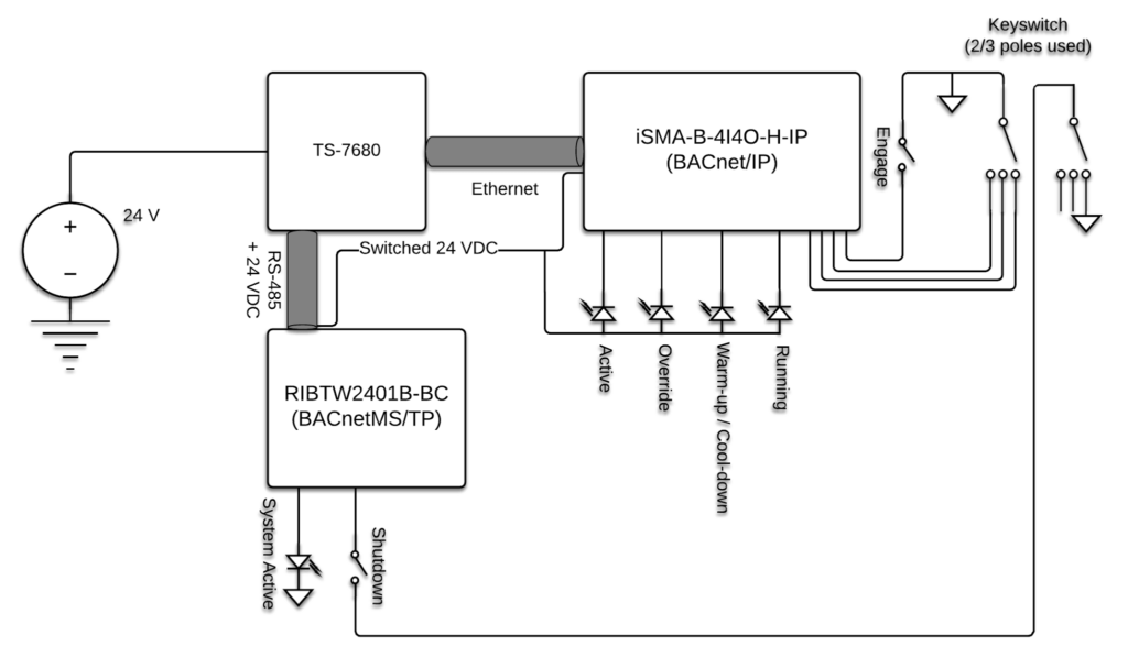

The whole demo is set to be controlled by the TS-7680. The TS-7680 takes 24 VDC input, enables the switched power to the BACnet modules, and handles communication with the two modules via the physical RS-485 and Ethernet interfaces. All of the I/O for the system is connected to the BACnet modules themselves and not the TS-7680.
When software control enables the switched power, it supplies the power to first module vis the RS-485 cable and is daisy chained to the second module. From the second module, the switched 24 VDC is routed to the control box.
In the BACnetMS/TP module, the System Active LED has power switched through the relay. This is wired internally in the enclosure. The Shutdown button is electrically in series with one of the keyswitch poles. The module’s dry-contact input is only fully closed when the keyswitch on the control box is in the Disabled position, and the Shutdown button is depressed.
All of the LEDs in the control box are wired to be common anode from the switched 24 VDC input, with each of their cathodes being connected to a relay output on the BACnet/IP module. When one of these relays is engaged, it allows the respective LED to illuminate. A ground connection is run from the BACnet/IP module to the common contact of the keyswitch and one contact of the Engage button. The three keyswitch contacts and the other contact of the Engage button are run to four independent dry-contact inputs on the BACnet/IP module. In this configuration, each keyswitch position will activate an input. This allows for the software to detect a wiring error at the added cost of an additional input being consumed in the BACnet module. Home