
Imagine this: You have a five-year-old son who has grown tall enough, and smart enough to open the door to your home office, packed with all your super fun gizmos and trinkets. It has a lock, but being the lackadaisical creature you are, you forget to lock it. You’ll only be gone for a minute or two, after all! Well, that was just enough time for your son to sneak in, rip up all the jumper wires from your breadboard, find a permanent marker, and well, you know how this ends.
In this (oddly specific) example project we’re going to be coming up with a solution to avoid such a disaster by building a wireless, internet connected, SMS door alert system using:
- 2x XBee Pro S1 Radios (OP-XBEERADIO)
- Sparkfun XBee Explorer USB
- TS-7553-V2 Single Board Computer
- Magnetic Door/Window Switch
- 3.7 VDC 1 Ah Lithium Polymer Battery
- Jumper wires and breadboard for prototyping
- PCB Etching
- 3D Printing
This way, we’ll receive a text message every time the door is opened and be able to rush to the scene of the future crime.
Before we begin, be sure you have a familiarity with connecting XBee radios by checking out the guide “A Friendly XBee Introduction”. Also, understand this guide is applicable to any single board computer or computer that has a XBee radio socket. It’s also just a very simple proof of concept design that could be taken a whole lot further in a whole bunch of directions using all sorts of sensors.
Okay! Let’s disappoint a five year old! Home
Lay of the Land
We’re after a simple solution, one that doesn’t take a lot of time, but also looks good when finished. So, this means we’ll want to have a nice looking enclosure to mount to the back of the door and no external wires if we can help it. The sensor is easy: we’ll just use a cheap magnetic door switch (aka reed switch). For the communication part, the TS-7553-V2 is an XBee ready single board computer that will act very nicely as a wireless gateway to send our alerts from over the Internet. XBee radios are small, require very little power, and are easy to use. This means, we can easily mount a small enclosure on our door and power it using a battery. Excellent! We’re now ready to start our proof of concept by getting the two XBee radios to talk to each other.
Pro Tip: As mentioned in the friendly introductory guide, save yourself some headaches and label your XBee radios in order to tell them apart. A piece of tape or tiny post-it note and permanent marker will do just fine. Label one with “C”, for “Coordinator” and the other with “ED”, for “End Device”. You could also write the MY, 16-bit Source Address, for extra clarity.
Buzzing XBee Radios
There will only be two XBee radios in this project. One will be configured as a coordinator and the other as an end device. The coordinator will be installed on the TS-7553-V2 and the end device will be in our door sensor enclosure. The end device will need to communicate to the coordinator when the door is open and the coordinator will need to be listening for this and execute some print_data() function that will later become our send_alert() function. So, here’s how we set up the two radios.
End Device Configuration
As mentioned before, the end device will be responsible for transmitting data to the coordinator when the door is opened. Since it’s connected to a battery, it needs to be in a low power mode. Looking through the XBee manual, it looks like pin hibernate mode is perfect, requiring < 10 µA. We can hook up the magnetic door sensor in such a way that hibernate mode will be active when the door is shut and inactive when the door opens. Next, we need to let the coordinator know when the door opens, so we’re going to send a periodic signal. XBee provides a method for transmitting all input signals every 20ms, which is perfect (IR). So, we’ll also want to configure at least one DIO as input. Let’s pick on DIO0 (D0) and configure it as digital input. It doesn’t much matter what the input is, but since it makes sense to read “True” in a script when the door is open, let’s just tie it to 3.3 VDC. So, to recap:
- Use hibernate pin connected to magnetic door sensor (SM = 1)
- Send periodic input signal readings (IR = 0x14)
- Use DIO0 as input signal, tied to 3.3 VDC (D0 = 3)
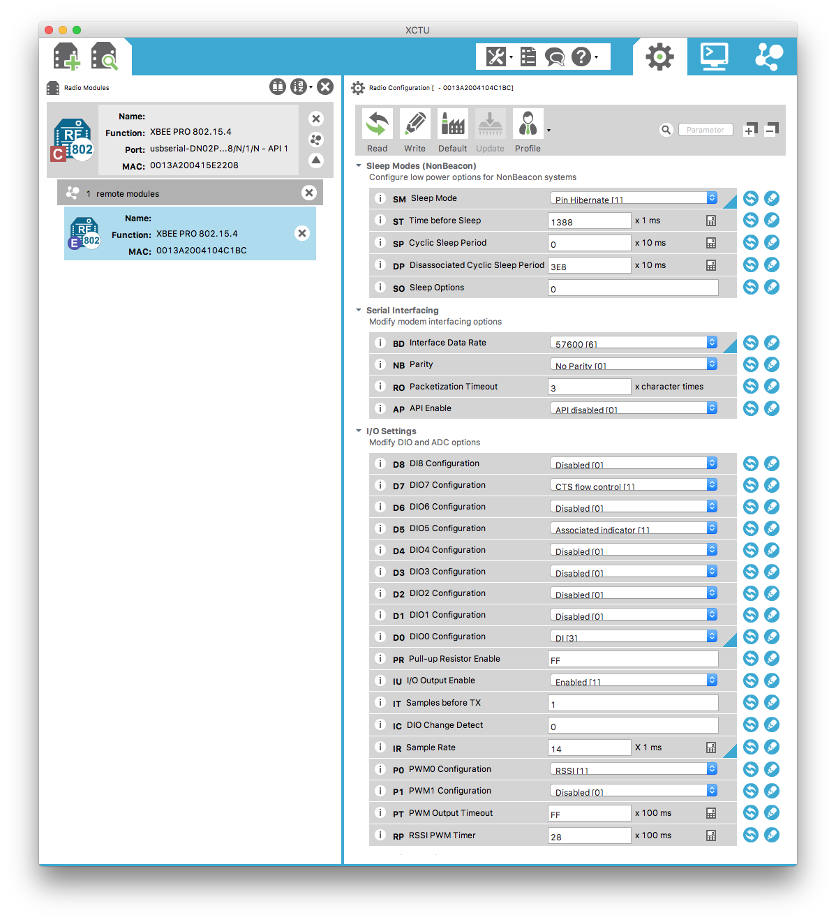
Coordinator Configuration
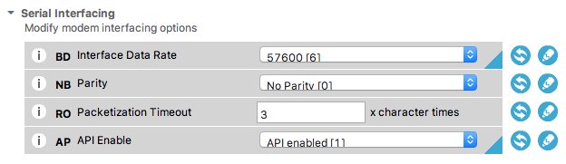
The only thing we need to do with the coordinator is enable the serial interfacing API operation. This is so we can use data API frames in our script later on. To recap:
- Enable the serial interfacing API operation (AP = 1)
Pro Tip: Since this will be connected to the TS-7553-V2, we will need to cut or bend pin 8 to avoid some hardwired conflicts (to be fixed in a later revision).
Circuit Design Work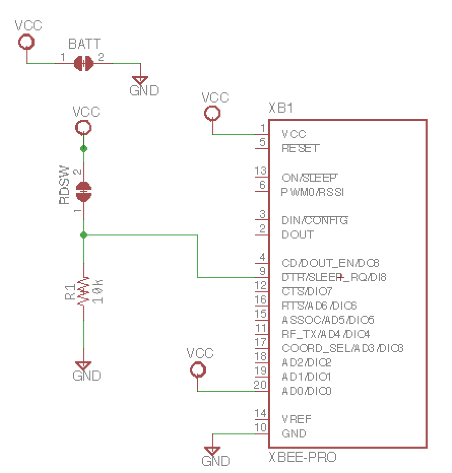
There are two main points of interest here: one is to put the radio to sleep when the door is shut and the other is to tie DIO0 to 3.3 VDC. The rest is to simply power the radio (3.3 VDC and GND). So, it should be a fairly simple schematic. Let’s use Eagle CAD software for the schematic and PCB design (later). The schematic is available in the resources directory of the embeddedts/xbee-door-alert repository. For now, you can take the schematic pictured above and translate it to a breadboard.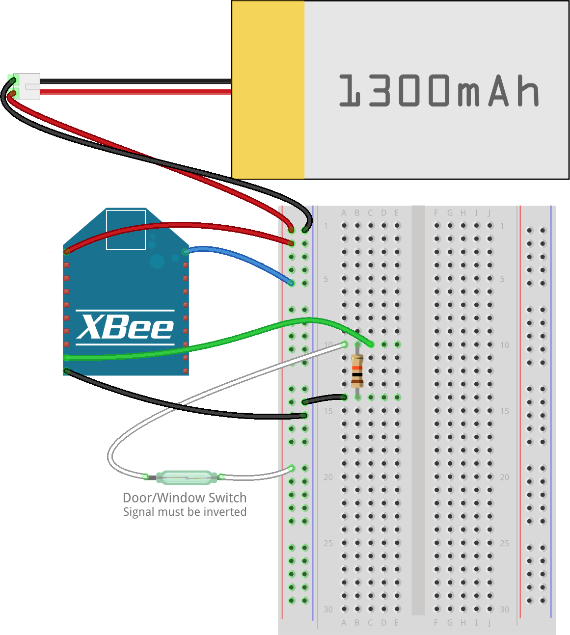
Sleep mode is enabled when SLEEP_RQ is floating or high and disabled when low. The magnetic door sensor, or reed switch, is connected when the door is opened. This means we’re going to need to use a pull down resistor so that sleep mode is disabled when the reed switch is connected (door opened) and enabled when the reed switch is open (door closed). This is the most complicated part of the circuit, so have no fears! The rest is self explanatory.
Naturally, there are opportunities for improvements here. For example, the battery is supplying a full 3.7 VDC and will drop below 3.3 VDC as it starts to drain. To properly power this circuit, we should have a buck regulator, like the TPS61200, in between the battery and XBee radio. Furthermore, we should be able to easily recharge the battery without needing to open the enclosure each time. So, some charging circuitry, like the MCP73831T, should be added and brought out to a micro USB header. Further improvements would include a status LED and MMS-110-01-L-SV XBee socket connectors. All of these improvements require more glue logic/components which is well beyond the scope of this project. For now, we just want it to work and keep things simple. Even without the regulator, at < 10 µA using a 1000 mAH battery, we should have a lot of time between charges.
With this out of the way, we’re ready for prototyping and software.
Scripting the TS-7553-V2 for Listening


We’re going to use Python since it’s such an easy language to grasp and offers so much in terms of third party libraries. In particular, the blalor/python-xbee library, which has several example scripts to start from, will make very quick work of the XBee communication portion of our script. We’ll also be sending out an email or SMS text message whenever the door is opened, so the standard library smtplib will make that easy.
All we need is to initialize our XBee socket and serial port, listen for data, and then send the alert via email to a specified address. To make this easy, we’ll use Gmail’s SMTP server instead of setting up the TS-7553-V2 as an email server. The specified address can be a traditional email address or it could be to a SMS/MMS email gateway provided by your wireless carrier. For example, if your number is 555-123-4567 and your provider is Verizon, you could send an email to 5551234567@vtext.com. Here’s a (non exhaustive) list of gateways for convenience. Home
Let’s start simple and see if we can receive data from the XBee end device and print it to the terminal. Here’s the script that will do that:
import serial, os, time
from xbee import XBee

# Need to be sure to reset the XBee radio socket before starting
# Specific to TS-7553-V2.  May not be required on other systems.
os.system("echo 0 > /sys/class/leds/en-xbee-3v3/brightness")
os.system("echo 1 > /sys/class/leds/en-xbee-3v3/brightness")

# Device name ttymxc7 is specific to TS-7553-V2. Refer to your
# boards manual.
serial_port = serial.Serial('/dev/ttymxc7', 57600)

def print_data(data):
    """
    This method is called whenever data is received
    from the associated XBee device. Its first and
    only argument is the data contained within the
    frame.
    """
    print data

xbee = XBee(serial_port, callback=print_data)

while True:
    try:
        time.sleep(0.001)
    except KeyboardInterrupt:
        break

xbee.halt()
serial_port.close()
When we run this script using python xbee-door-alert.py, we should see output similar to this when our reed switch is disconnected or the door is opened:
root@ts-imx6ul:~# python xbee-door-alert.py
{'rssi': "'", 'source_addr': '\xbe\xef', 'id': 'rx_io_data', 'samples': [{'dio-0': True}], 'options': '\x00'}
...
What we’re interested in is seeing the value of dio-0 in the samples array. Since it’s value is True, we know the XBee is awake and transmitting data successfully!
The next step is to get email working. Mainly, this requires creating a new send_alert() function and change the callback from print_data to send_alert. The send_alert() function looks like this:
def send_alert():
# For security, let's grab credentials from a config file.
# Copy config.example.ini to config.ini with your info.
config = ConfigParser.ConfigParser()
config.read("config.ini")
gmail_user = config.get('Credentials', 'Username')
gmail_password = config.get('Credentials', 'Password')
to_email = config.get('Email', 'to')
try:
server = smtplib.SMTP_SSL('smtp.gmail.com', 465)
server.ehlo()
server.login(gmail_user, gmail_password)
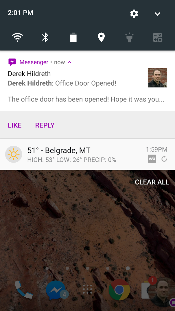
msg = MIMEText("The office door has been opened! Hope it was you...")
msg['Subject'] = "Office Door Opened!"
msg['From'] = gmail_user
msg['To'] = to_email
server.sendmail(gmail_user, [to_email], msg.as_string())
server.close()
print "Alert email sent!"
except:
print "Something went wrong in send_alert()!"
print sys.exc_info()[0]
raise
For full context, please see the example source code which has been published at GitHub in the embeddedts/xbee-door-alert repository. Example system init scripts for running the script on startup are also included in that repository.
And, that’s it! Our email configurations are saved in a file called config.ini which makes it easy to customize and secure to keep in a public github repository. You’ll want to set it up with your own email information and test to make sure it works. If all goes right, you’ll get an email or SMS text message alert on your phone!
Next, let’s work on getting a prototype built so we can install our solution! If you’re just here for the introduction of getting XBee radios to communicate with one another, you can stop here. If you’re the sort of person who enjoys the making process, then please continue on! We’ll be playing with homemade PCBs and a 3D printed enclosure to put everything in.
PCB Design Work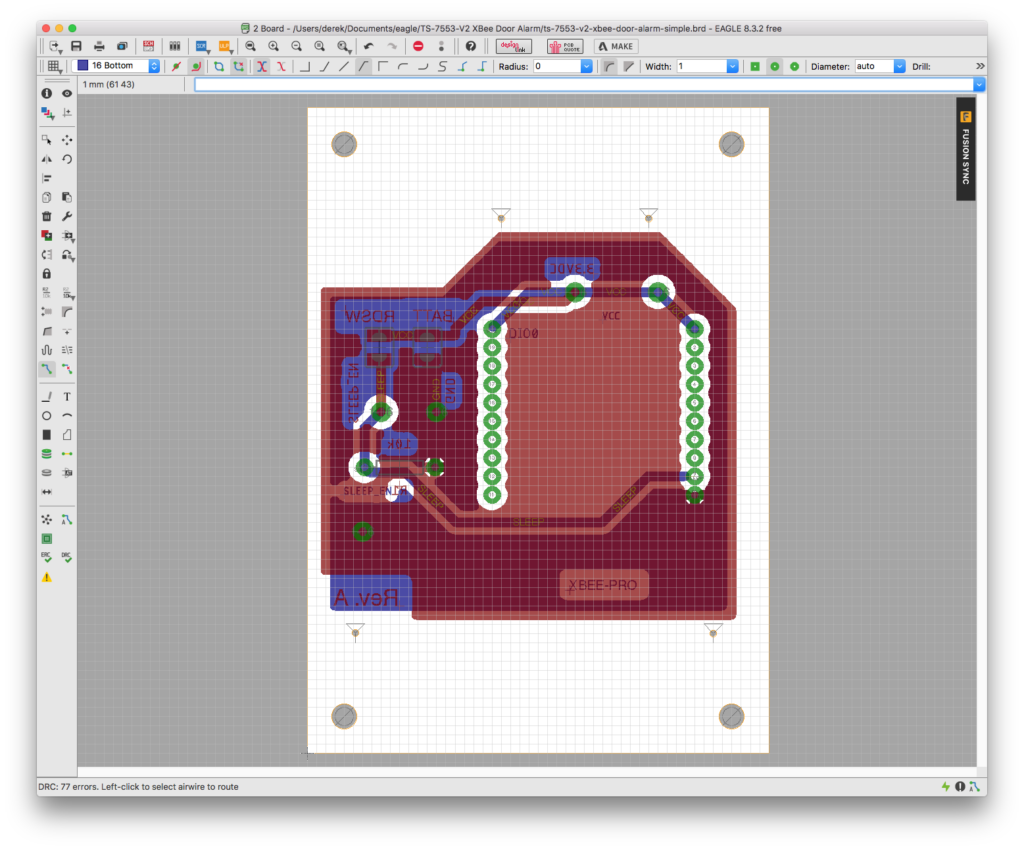

Once again, we return to Eagle CAD for PCB designing. Let’s not get tangled up in too much details since this could a complete guide all on its own, but the schematic, PCB design, and design rules are all available in the embeddedts/xbee-door-alert repository, so be sure to clone it and import the design rules (Edit -> Design Rules -> Import). The design rules are setup for PCB etching at home using thermal transfer paper and ferric chloride copper etchant solution so that traces and pads aren’t too small to work with.
Once Eagle has a schematic and board linked up, it’s relatively easy to create a PCB layout by using the auto router or by making your own. There are plenty of tutorials and videos available for this, so don’t be shy to search around. Our PCB will be 50 mm x 70 mm with four mounting screw holes.
PCB Etching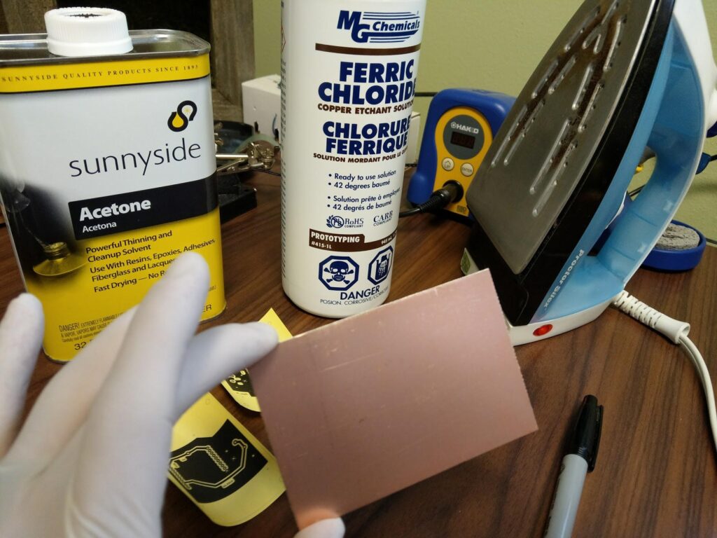

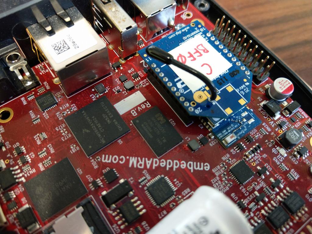
Once the PCB design is completed in Eagle, print to the thermal paper and prepare for etching to a double sided copper clad PCB. Be sure to include some holes to align both layers. Use a permanent marker to fill in any gaps that didn’t transfer and then use the ferric chloride to remove all the copper except what’s under the permanent marker. Home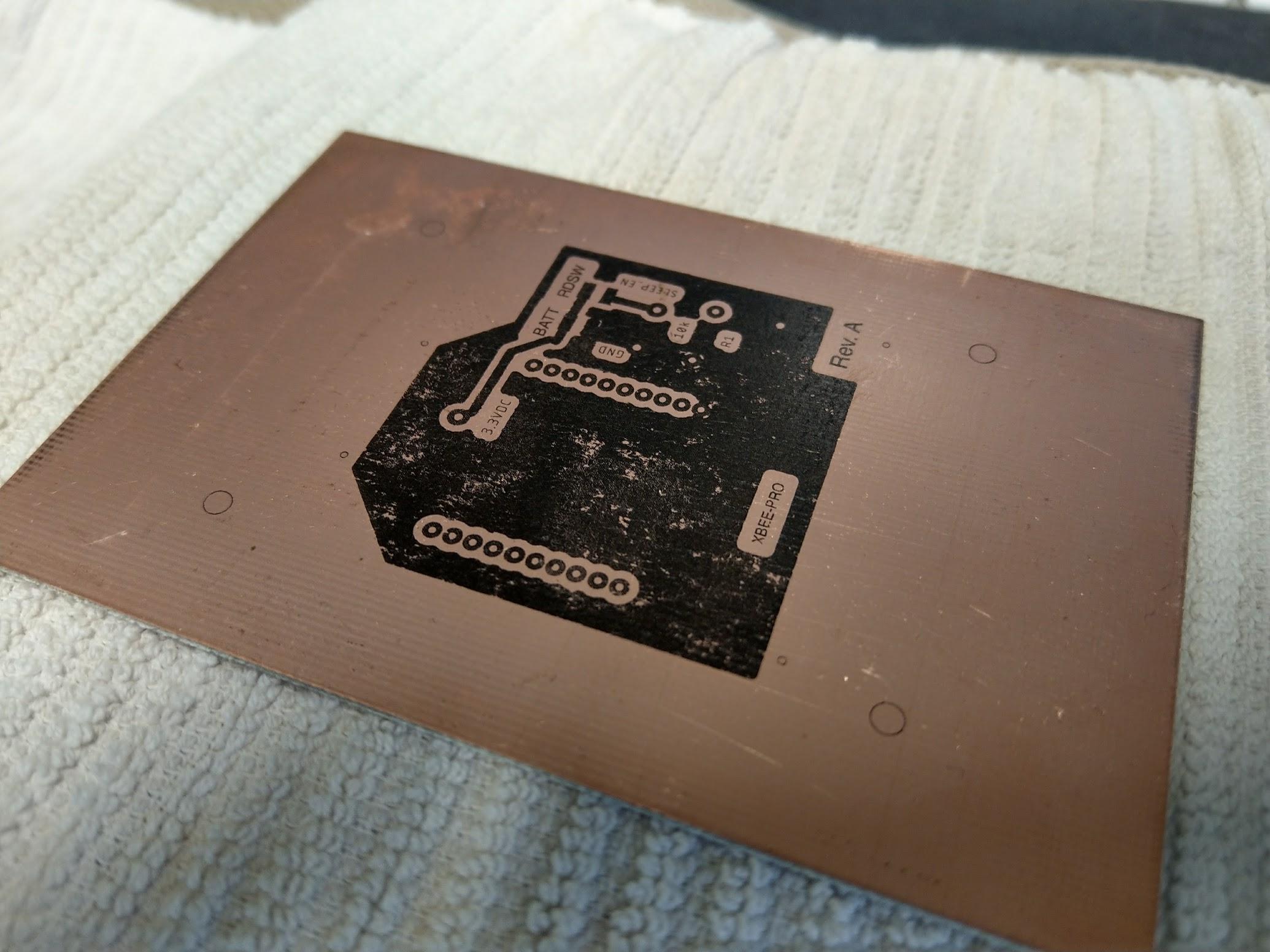
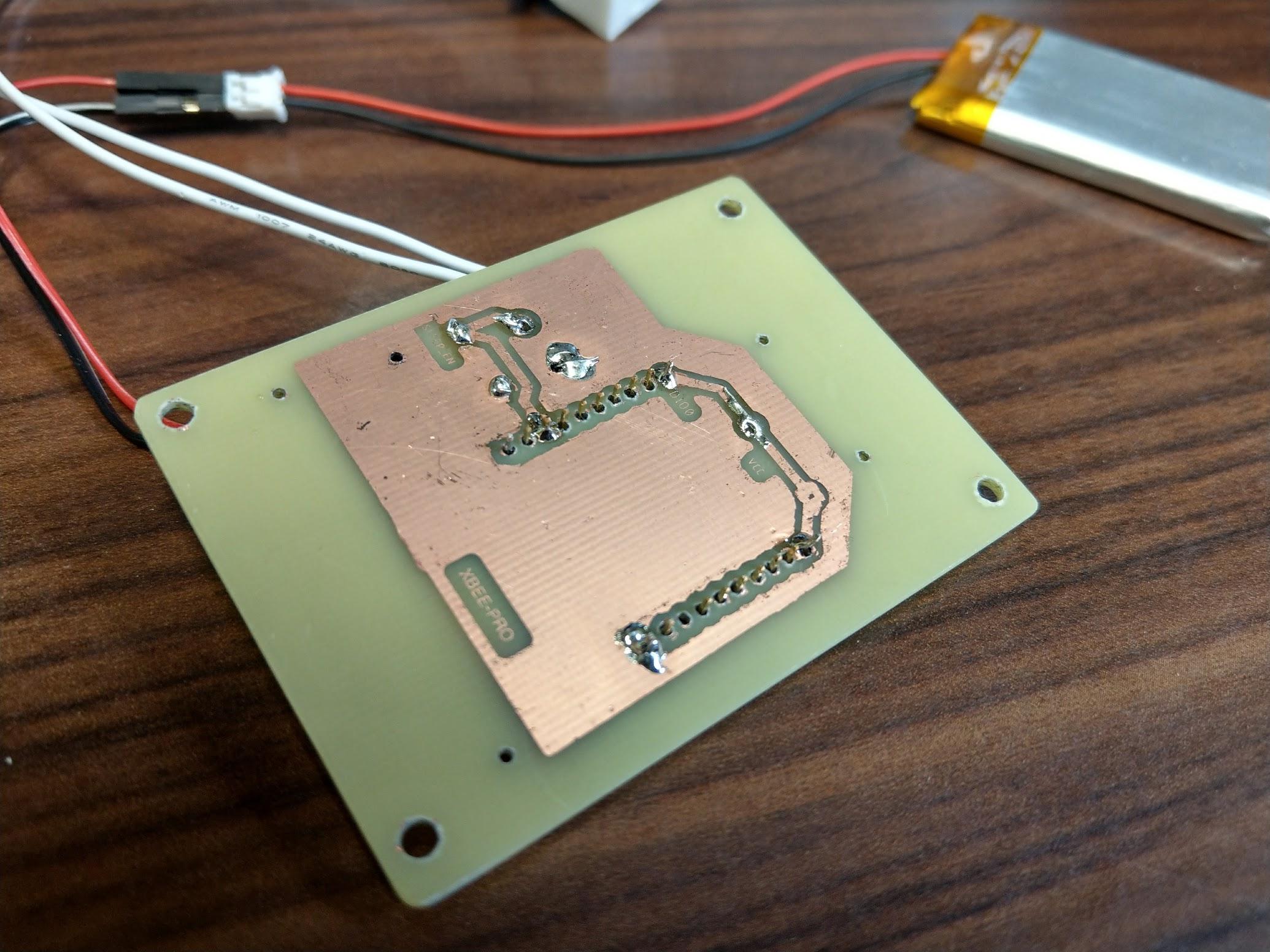
Here’s what the final product should look like after the etching process and the components have been soldered on.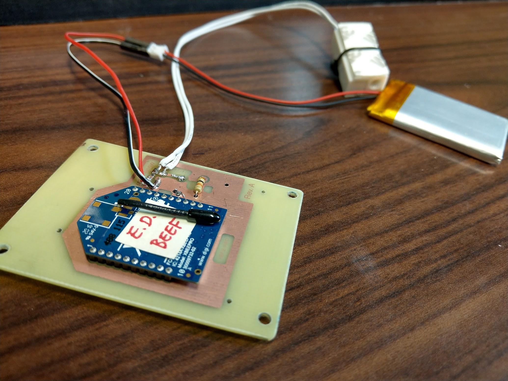
 Great! We’re now ready to put our solution into a nice enclosure of our own design.
The Enclosure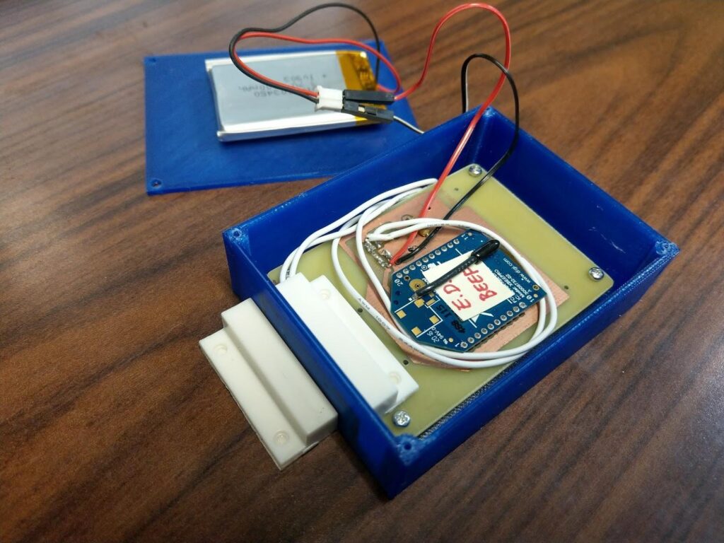

There are lots of engineers who to keep a tidy office (there are dozens of us!), so we want to keep our solution enclosed and hide those unsightly wires. What better way than to flex our geek muscles and up our street cred by using a 3D printer to make our own! It starts by opening a 3D CAD program and start designing.
3D Design
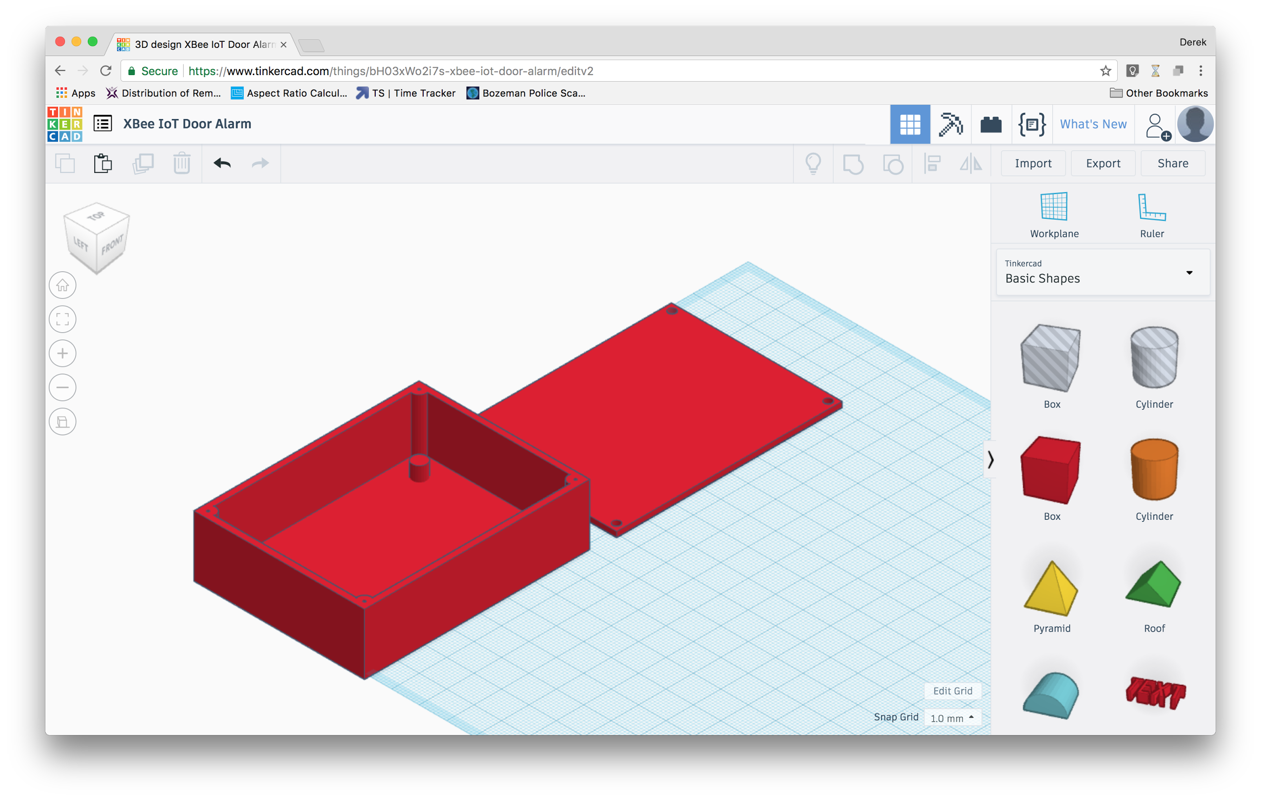
This isn’t meant to be an official endorsement, but Tinker CAD is a fantastically simple web program that makes it easy to design and print 3D models. You may have your own preferred program, but if you’re just starting out, give Tinker CAD a shot. You can view the 3D model for this enclosure at the link https://www.tinkercad.com/things/bH03xWo2i7s.
For this enclosure, we need to fit the battery (34 mm x 52 mm x 6 mm) and PCB with XBee radio (50 mm x 70 mm x 7 mm). We’ll use 1.8 mm for wall thickness, 5 mm offsets and 3 mm screw holes, both with 1 mm pilot holes. It helps to create these parts in the model to make sure it’ll all fit properly since you can virtually drop them into the enclosure (see image below).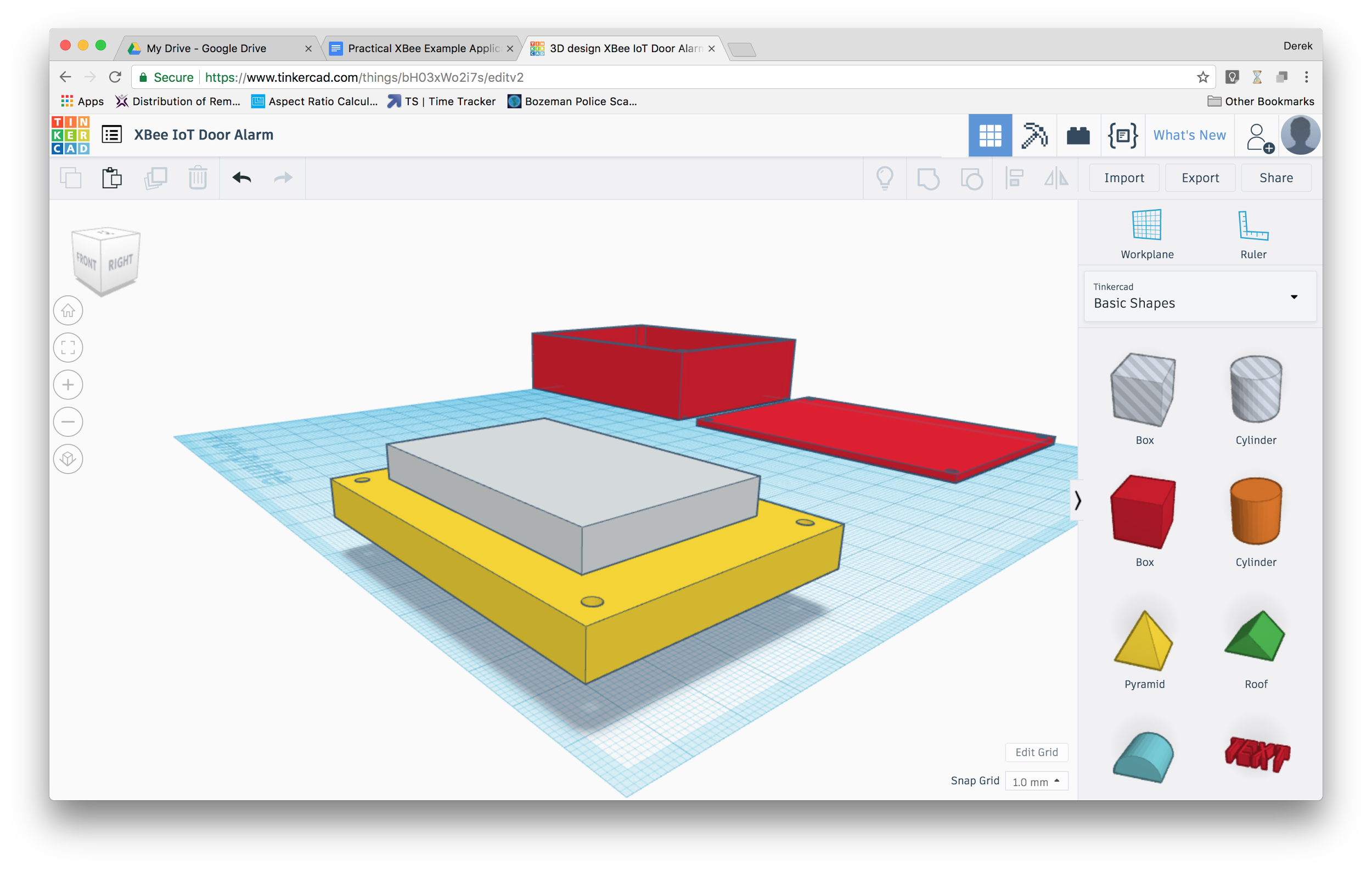
Once we’re happy with our enclosure model, it’s time to print!
3D Printing
[gfycat data_id="RequiredLawfulDikkops"]Once again, Tinker CAD makes it easy to export to a STL file, which is a common filetype for 3D printers. If you don’t own your own 3D printer, you can always send it out using any of Tinker CAD’s partners. We happen to have access to a 3D printer at Technologic Systems’ headquarters, so we’ll take advantage of that.
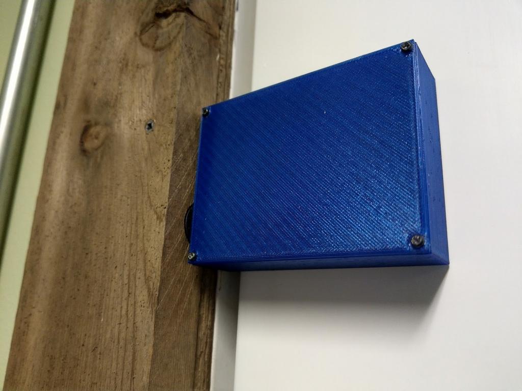
The finished product is able to hold all of our components, including one side of the magnetic door sensor. Double sided tape secures the sensor to the inside wall of the enclosure and screws secure the rest to the enclosure.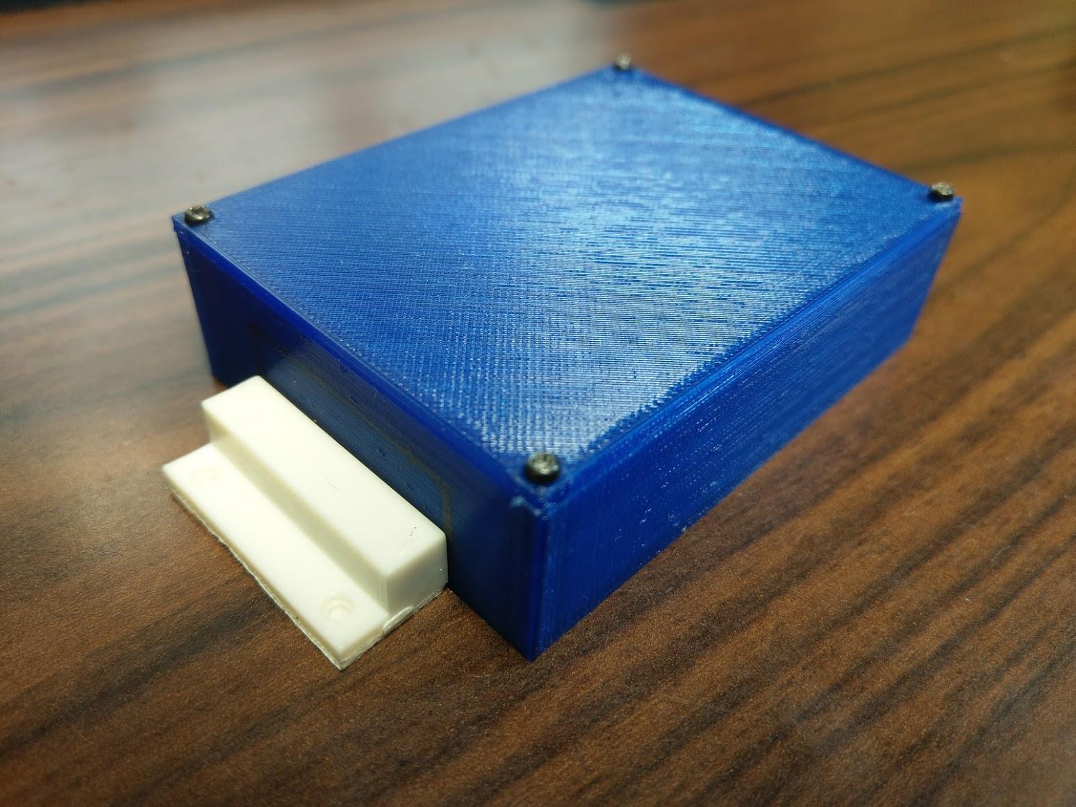
Finally, it’s time for installation! Mount the magnet to the door frame and the enclosure to the door using double sided tape, and give it a test run by opening and closing the door!
Pro Tip: To test the magnet placement, temporarily modify the script to use the print_data callback so you can see in real time when the door is open and shut. Tweak enclosure and magnet position until it works the way you want it to.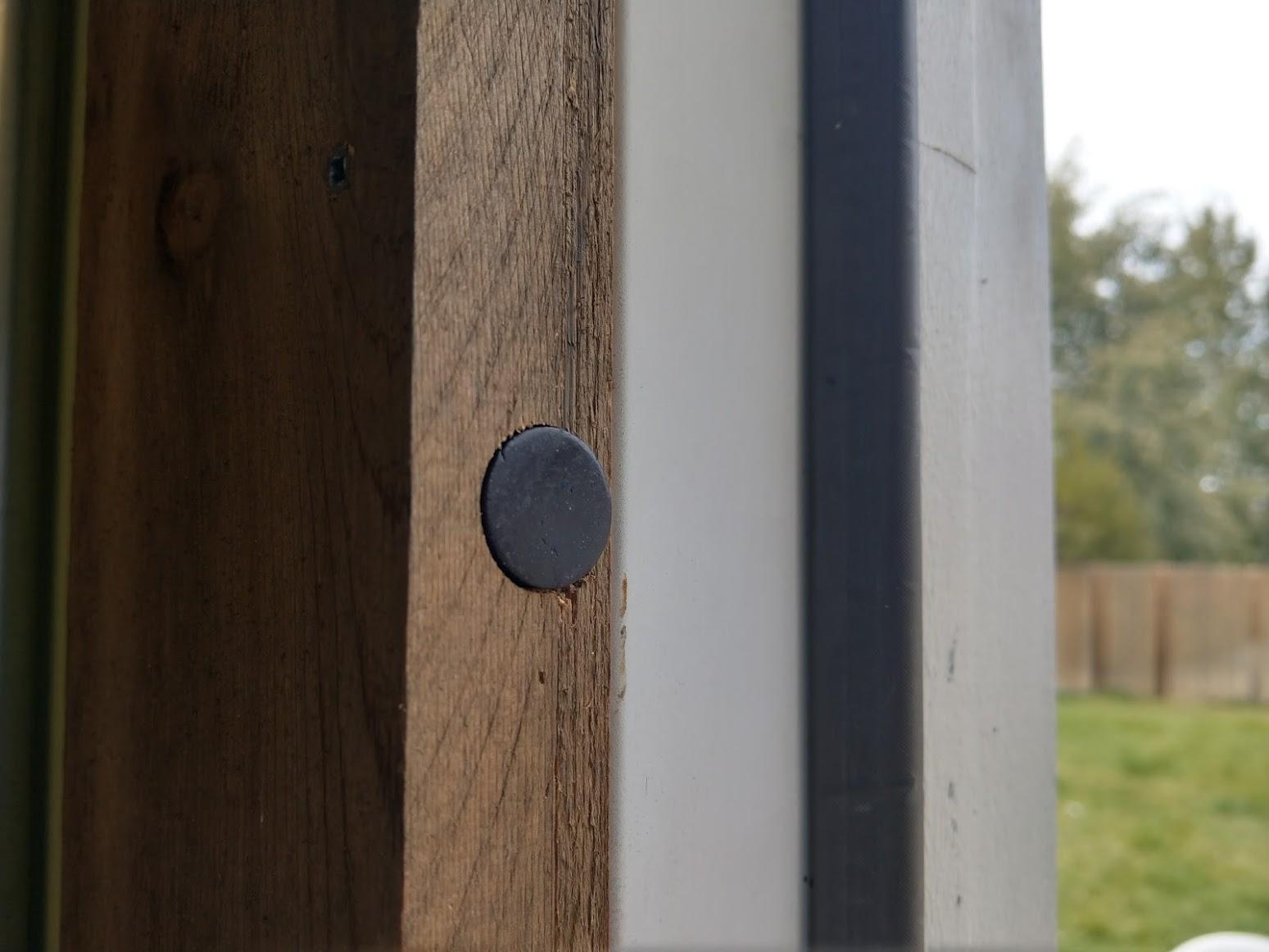
For myself, the trim around the door was too thick and wouldn’t allow me to mount the second half of the magnetic door sensor. So, instead, I used a strong magnet and embedded it into the trim by using a wood boring drill bit.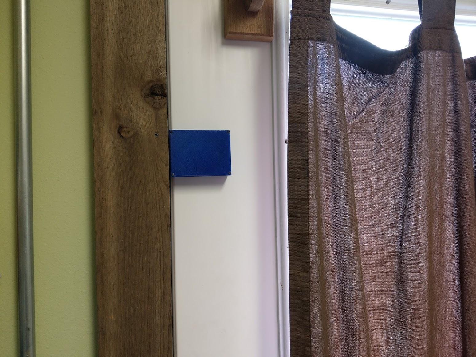
With that, we’re done!
Conclusion

The final product is a nice looking, wireless door sensor that sends an SMS/email alert message every time the door is opened. WIth this example application, you should now have a good understanding of how to wirelessly transmit data using XBee radios. Of course, this is just the beginning of what you could accomplish with an internet connected, single board computer like the TS-7553-V2 and wireless technology like XBee, so get brainstorming on what you could do.
As for myself, I accomplished what I set out to do. Now, that little rascal doesn’t stand a chance at getting to daddy’s office toys collectibles!
Lessons Learned
- Can’t leave the door opened for fresh air
- I get an email alert on my computer every time I enter. Would be neat to use RF tags or something to identify myself with.
- Could’ve made it smaller and rounded edges.
- Could’ve used a photosensor instead of a magnet.
- Could’ve mounted the box anywhere if I was willing to run wires to sensor.
If you have any comments, good or bad, please share with me and the Technologic Systems’ community! I’d love to hear from you and I’d love for you to share and use as a resource for your next project. Home