Let’s take a quick look at what it takes to read from the ADC inputs of a i.MX28 based embedded system using example C code provided by Technologic Systems. Now, while this can be generically applied to many i.MX28 based embedded systems, we’ll be working with a TS-7680. Right, let’s get started!
Hardware Hookups
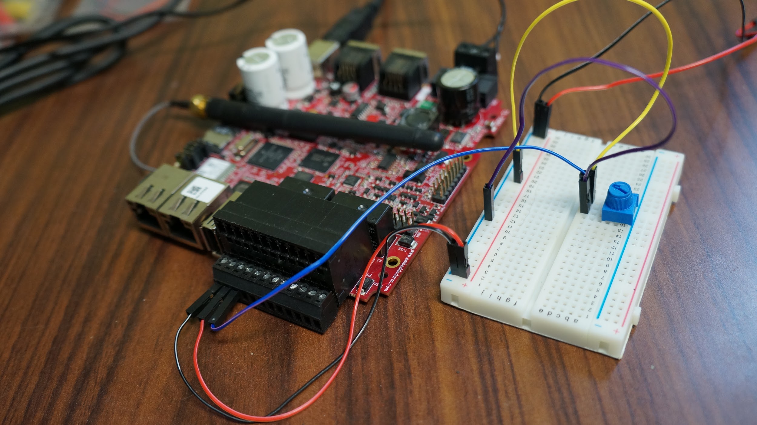
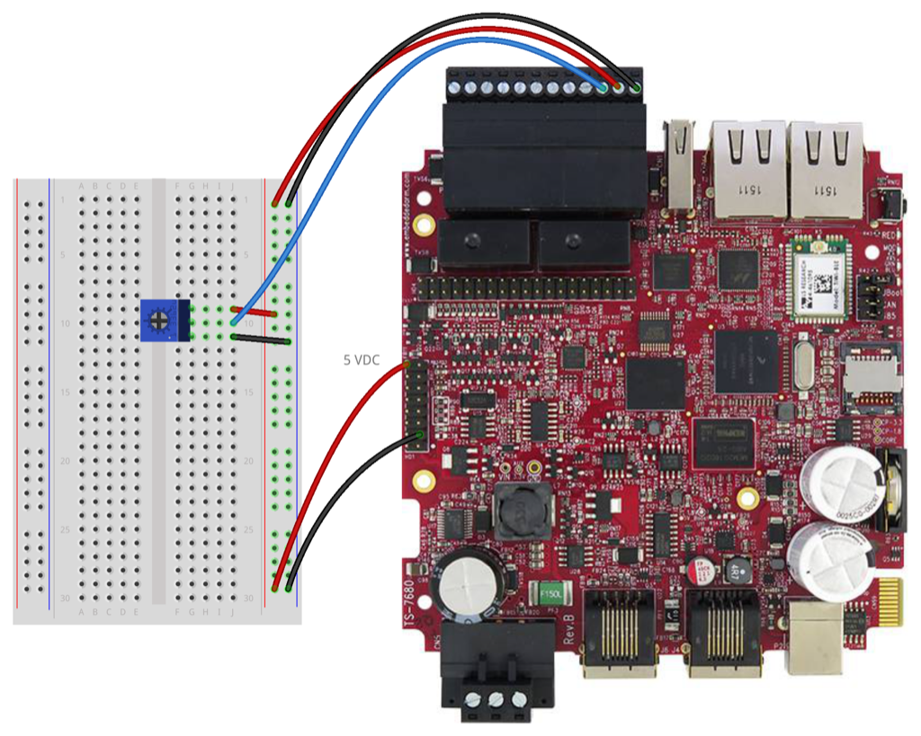
Before we dive into software, let’s take a look at our hardware. On our TS-7680, the four ADC inputs are located on the bottom screw terminal connector. Referring to the TS-7680 schematic, we’ll find these pins are connected to the CPU ADC pins with some glue logic in between, enabling 4 – 20 mA and 0 – 10 VDC inputs. For our example code testing purposes, we’ll be working with 0 – 5 VDC input. Take a look at the wiring diagram below for how we’re going to hook everything up. We’re going to use the 5 VDC pin of the HD1 header. You’ll see we’re using a trimpot located on a breadboard to vary our input voltage from 0 – 5 VDC on the pin labeled AN-1. For AN-0, we’re going to use constant 5 VDC. Of course, we’ll need to connect the pin labeled GND to, well, ground (also provided by the HD1 header). That should do it!
 Jumping into Code
Now, the fun part. I’m going to assume you already know how to console or SSH into the board you’re working on since we’re going to be compiling everything onboard. If you’re on a TS-7680, and you don’t have either of these things, you can refer to Practical Guide to Getting Started with the TS-7680. Right, so let’s start by finding a spot for our example code and downloading it onto our board. I’m going to call it getadcsince it’s easier to remember and type than mx28adcctl.
mkdir ~/getadc
cd ~/getadc
wget ftp://ftp.embeddedTS.com/ts-arm-sbc/ts-7680-linux/samples/mx28adcctl.c
cp mx28adcctl.c getadc.c
Okay, with that out of the way, let’s take a look at what we’re about to compile. You can use vim, nano, cat, less, or whatever to view the file getadc.c. You’ll notice there’s a nicely commented section about the program, what it does to obtain the voltage input values, and the different calculations for different platforms. You’ll also notice the output will be in mV, in order to avoid any floating point arithmetic. For the sake of convenience, here it is: Home
/* This is where value to voltage conversions would take
 * place.  Values below are generic and can be used as a
 * guideline.  They were derived to be within 1% error,
 * however differences in environments, tolerance in components,
 * and other factors may bring that error up.  Further calibration
 * can be done to reduce this error on a per-unit basis.
 *
 * The math is done to multiply everything up and divide
 * it down to the resistor network ratio.  It is done
 * completely using ints and avoids any floating point math
 * which has a slower calculation speed and can add in further
 * error. The intended output units are listed with each equation.
 *
 * Additionally, since very large numbers are used in the
 * example math below, it may not be possible to implement the math
 * as-is in some real world applications.
 *
 * All chan[x] values include 10 samples, this needs to be
 * divided out to get an average.
 *
 * TS-7682
 *   LRADC channels 3:0
 *     0 - 12 V inputs, each used channel must have the En. ADX bit set
 *       in the FPGA Syscon before the channel can operate properly.
 *     The achievable accuracy is within 5% for each channel without
 *       further calibration.
 *     chan[x] mV = (((chan[x] - 52) * 10000) / 3085)
 *
 * TS-7680
 *   LRADC channels 3:0
 *     PCB [Rev C] or [Rev B with R134-R137 removed]:
 *       0-10 V in. chan[x] mV=((((chan[x]/10)*45177)*6235)/100000000);
 *       4-20 mA in. chan[x]:
 *         meas_mV=((((chan[x]/10)*45177)*6235)/100000000);
 *         uA=(((meas_mV)*1000)/240)
 *     PCB [Rev B]:
 *       Note: R134-R137 are intended to add bipolar input to the
 *       existing channels.  The FETs must also be removed in order to
 *       correctly handle a negative input voltage.  The default
 *       Rev B PCB configuration has these resistors installed.  Either
 *       they must be removed, or the FET on each channel.  And the
 *       math can either use the above numbers, or a tuned equation
 *       to handle their bipolar behavior.
 *
 * Other i.MX28 based SBCs
 *   LRADC channels 4:1
 *     chan[x] = ((((chan[x]/10)*45177)/100000)*2);
 *   LRADC channel 6
 *     chan[x] = ((((chan[x]/10)*45177)/1000000)*33);
 *   HSADC
 *     chan[7] = ((((chan[7]/10)*45177)/100000)*2));
 */
Directly following this comment block is the code that loops through all seven ADC inputs of the i.MX28 CPU, calculates the voltage input values based on what was said in the comments, and spits out their values to the console.
for(x = 0; x < 7; x++) {
    printf("LRADC_ADC%d_val=%d\n", x, (unsigned int)chan[x]/10);
}
printf("HSADC_val=0x%x\n", (unsigned int)chan[7]/10);
If we were to look at the rest of the code, it probably feels overwhelming. There’s a lot of code involved with setting up registers and whatnot. Let’s not get too caught up in this as we might lose sight of the end goal. Just know it’s necessary to set ourselves up for reading ADC input values of the i.MX28. If you’re really curious, you could find this information available in the i.MX28 datasheet. For now, it’s enough to see that for our TS-7680, we need to use the formula already calculated for us by Technologic Systems’ engineering:
mV=((((chan[x]/10)*45177)*6235)/100000000);
So, we’ll modify the printf statement from within the for loop to read:
printf("LRADC_ADC%d_val=%d\n", x, (unsigned int)((((chan[x]/10)*45177)*6235)/100000000));
Save the file and let’s try to compile. As written in the comment header, to compile, we use:
gcc -fno-tree-cselim -Wall -O0 -mcpu=arm9 -o getadc getadc.c
Pro Tip: The gcc arg -fno-tree-cselim is required to avoid a nasty bug when using the volatiletype.
Hooray! If all went well, you should now have a new getadcbinary to run. With our hardware all setup, and our trimpot turned down slightly from 5 VDC, you should get output similar to this:
root@ts7680:~/getadc/# ./getadc
LRADC_ADC0_val=5011
LRADC_ADC1_val=2334
LRADC_ADC2_val=0
LRADC_ADC3_val=0
LRADC_ADC4_val=0
LRADC_ADC5_val=0
LRADC_ADC6_val=0
You can validate using a multimeter and you’ll find it to be accurate. At this point, you’re ready to move onto modifying the example code to suit your particular needs. For example, maybe you want to copy getadcinto your PATH and use it to obtain a single ADC pin value. Oddly specific, right? That’s because I used it this way in another project. You can find the Makefile and getadc.c files all right here in GIT so you can get a head start.
If I’ve left anything out or you’re still yearning for knowledge, please leave a comment below or contact engineering directly using the contact form in the sidebar. Home
Happy coding!
Thanks for sharing such an informative blog . The blog also provides information about hardware hookups and code used in it. This blog will be helpful to many people who wants to know about embedded system.
Thanks for sharing this useful information about c-code-for-reading-adc-inputs-on-i-mx28-based-embedded-systems which is help more as well as other students and professionals also.
http://www.traininginlucknow.in/best-embedded-system-training-in-Lucknow.html