Introduction
This is a developer’s note about rewriting the Application Programming Interface (API) for the TS-ADC16 and TS-ADC24 PC/104 peripherals. With the existing API being written in 2010 it was decided that a rewrite would be more effective than a comprehensive update. This article will cover the details of the development for the new API and also briefly describe the functions in the API.
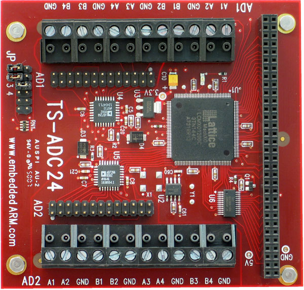
Our ADC Devices
Both the TS-ADC16 and TS-ADC24 are PC/104 peripheral boards that can take data samples from multiple inputs and store them in a 512×16-bit FIFO built in to the on-board PLD. They will work with nearly all PC/104 masters in 8-bit mode, and is compatible with Technologic Systems’ PC/104 SBCs in 16-bit or 8-bit mode. The TS-ADC16 and TS-ADC24 provide 16 and 24 input channels respectively up to 2 MS/s, making them ideal devices for digital signal processing.
Pro Tip: The 16-bit mode is specifically designed to work with Technologic Systems’ products, but that isn’t to say it won’t work on different PC/104 boards as well.
Registers Accessing
The TS-ADC16 and TS-ADC24 has multiple 16-bit registers to which you can find information about each bit in the TS-ADC16 or TS-ADC24 manuals. The memory management declarations library provided in C, <sys/mman.h>, is used by the API to access these registers. Once you set the correct memory address, you can read or write to the registers. It is very important to read the manuals and know the details of each bit in every registers. Writing unexpected information to registers could cause unknown issues and may damage the devices.
Pro Tip: Each SBC has its own 8-bit, 16-bit PC/104 I/O address and each PC/104 peripheral has its own base address base on the jumper setting. Be sure to modify the example code with the I/O address for your board.
FIFO
The FIFO in both ADC peripherals will start collecting data samples once the SYSCOM (aka state machine bit) bit is set to 1, initializing the internal state machine. The FIFO will stop collecting data when the state machine stops under two conditions: 1) when SYSCOM is set to 0, or 2) when the FIFO is full. The number of channel pairs need to be specified before starting the state machine. Information regarding channel pairs can be found in the TS-ADC16 and TS-ADC24 user manuals.
Pro Tip: The FIFO can only contain up to 512 samples, and it can fill up really fast. For your development, watch for the speed of the sample ratings.
Easy Reading
We made the new API user friendly with lots of detailed documentation in the source code comment blocks. The API was written with meaningful and clear variable and function names. The documentation includes function descriptions, inputs, and return values as well as usage concepts and technical details of the ADC peripherals.
API Functions
TS-ADC16 and TS-ADC24
- adcSetup (adc_base, PC104base)
- Input: base register address of the ADC device, base PC104 I/O address for you SBC.
- Output: a pointer that can access registers on the ADC device (adc_io).
- This function will setup a pointer for accessing registers on the ADC device.
- adcStart (adc_io, channelNum)
- Input: pointer to ADC device’s registers, number of channel pair you want to be activated.
- Output: None.
- This function will start the state machine. You also need to specify how many channel pairs you want to be activated when using this function.
- adcStop (adc_io)
- Input: pointer to ADC device’s registers.
- Output: None.
- This function will stop the state machine.
- setClockSpeed (adc_io, speed)
- Input: pointer to ADC device’s registers, speed for sample rate.
- Output: None.
- This function will set the 24-bit pacing clock counter on the ADC device. Notes that in here, bigger number means slower sample rate.
- cleanFIFO (adc_io)
- Input: pointer to ADC device’s registers.
- Output: None.
- This function will empty the FIFO. Once this function is being called, it will read every sample that is remind in the FIFO and make sure that the FIFO is empty.
- Pro tip: Stop the state machine before using this function.
- setInterrupt (adc_io, level)
- Input: pointer to ADC device’s registers, the level to interrupt the ADC device.
- Output: None.
- This function will set in interrupt level for ADC device. Notes that the default is half full (256).
- getBoardInfor (adc_io)
- Input: pointer to ADC device’s registers.
- Output: None.
- This function will display the device information to the console.
- getFIFOcount (adc_io)
- Input: pointer to ADC device’s registers.
- Output: current FIFO count.
- getHeadChannel (adc_io)
- Input: pointer to ADC device’s registers.
- Output: the channel number in the head of the FIFO
- readFIFO_Data (adc_io)
- Input: pointer to ADC device’s register.
- Output: the first sample in the FIFO.
- This function will read the first sample in the FIFO and return it as a 16-bit number.
TS-ADC24
- Struct adcFIFO readFIFO (adc_io)
- Input: pointer to ADC device’s register.
- Output: struct adcFIFO that contain information read from the FIFO.
- This function will return a struct adcFIFO that contain a 12-bit data read from FIFO, a 3-bit data that indicated which channel is that data come from, a 1-bit data that indicated which adc chip is that data come from.
TS-ADC16
- getCount (adc_io, counter)
- Input: pointer to ADC device’s register, number of counter you want to read (0-3);
- Output: value of that counter that you are trying to read.
- setDAC (adc_io, dacNum, level)
- Input: pointer to ADC device’s register, the DAC you want to activated, level of voltage.
- Output: If succeed, return 1, else return -1.
- There are for DAC output on ADC16, using this function you can change their output voltage. dacNum should be between 0-3, level should be between 0xfff to 0x000.
- For DAC in 5V mode, 0xfff means 5V and 0x7fe for 2.5V and so on.
- setDIGIO (adc_io, output)
- Input: pointer to ADC device’s register, output to set Digital output to either 1 as high or 0 as low.
- Output: None.
- getDIGIO (adc_io, input)
- Input: pointer to ADC device’s register, input number that you want to read (0-3)
- Output: data read for the selected Digital input.
Conclusion
In this article, we discussed reasons for the TS-ADC16 and TS-ADC24 PC/104 peripheral API rewrite for additional reliability and usability as well as covered some details about the new API. We also briefly described the technical details of the API and where to find additional details. We hope this new API will help developers get their applications up and running quickly. Home