Introduction
We’re graduating from our Getting Started with Qt Creator on the TS-TPC-8390-4900 guide, where we ran an example program which came preloaded with Qt Creator on our TS-TPC-8390-4900, and moving into a more real world situation. This guide builds upon the foundations that we set up in the getting started guide and will walk you through building a simple human machine interface (HMI) for supervisory control and data acquisition (SCADA) applications. We’ll be controlling a register connected to a red LED as well as reading a temperature sensor connected to our CPU. This is about as basic as you can get to demonstrate both system control and data acquisition, and it’s not far from a basic real world use case. In the real world, you’d be toggling DIO or relays instead of toggling an LED. As an end user of the touch panel computer (TPC), you’d be transferring control signals or other data via RS-232 or Ethernet with the press of a button. Once you complete this tutorial it’s a small jump to toggle DIO and relays to control a remote system.
For this guide, a project file containing TS-TPC-8390-4900 specific code written in C++ called “HeatLaser” will be provided for you. It reads CPU temperature every second and toggles the red LED. You’ll simply download it and open the project within Qt Creator. By the end of this guide, you’ll be able to run and have a basic understanding of a Qt Quick Controls application. When you’re comfortable, you can make some edits to the project file to implement other similar tasks that may be more relevant to your needs.
[gfycat data_id="AridOrderlyGreatdane"]
Our Use Case

Let’s have some fun with this and set the stage. We own a temperature-sensitive facility on the planet Trisol (translation: three suns) which needs to have a minimum temperature of 40 °C (104 °F). It’s heated by three suns during the day, but has potential to drop below our threshold during the night. It’s heated by a laser-powered furnace. Shooting a high powered, red laser beam at the furnace causes it to warm up, much like a bellow and fireplace.
Against our better judgment for automation, we’ll hire a Trisolian to sit and monitor the temperature and press a button on the TPC to turn on or off the laser according to the temperature displayed.
Poor sap.
Anyways, let’s call our project the Trisol Heat Laser Controller, or HeatLaser for short.
Pro Tip: Binge watching Futurama on Netflix takes 1 day, 20 hours as of this writing. I’m not recommending you do this, but I’m not, not recommending it either!
Planning the Project
Going into this project, we already decided to use Qt Quick in order to get something to market quickly. Plus, we have handy all the cross compile toolchains and setup instructions in the both the TS-TPC-8390-4900 manual and Getting Started with Qt Creator on the TS-TPC-8390-4900 guide. We could’ve looked at using GTK or even Crank Software, so you may want to consider which avenue you’ll want to go down. Again, for this project, we’re going to be using Qt Creator to develop a Qt Quick Controls application.
Qt Quick applications offer a nice separation between the UI component on the frontend and the C++ code driving the backend. Frontend code is kept in a “.qml” file (Qt Meta/Model Language), and, linking the frontend with backend code is a file called “main.cpp”. It’s rather simplistic and short, and you can learn more about it by watching this video on Qt Fundamentals. More Qt fundamentals can be found on the Qt website as well as in this Qt for Beginners guide.
Another concept which helps in basic understanding is that Qt uses signals and connections to talk between backend and frontend. The connections are defined in the .qml frontend code and signals are defined in .cpp code. The backend code will “emit” a signal, and the listeners on the frontend catch them and handle it. So, I would create a signal called “timeUpdated”, and specify in the frontend to listen for “onTimeUpdated”. Then, I would do whatever with the data returned from the signal. You’ll see this when you look at the project code, so let’s dive in.
Diving In
If you’re coming from the Getting Started with Qt Creator on the TS-TPC-8390-4900 guide, you’ll probably have two development environments: a Windows or Mac OSX development machine for quick frontend iterations and a Linux VM for cross compiling and running on the TS-TPC-8390-4900. Preferably, you’ll have a single, non-VM Linux machine which you’ll be doing all development from. Either way, start off by booting your Linux development machine and launch Qt Creator. Download the HeatLaser project file HeatLaser.ziporHeatLaser.tar.gzand open it in Qt Creator.
If you’ve already proven your workflow and installation by successfully completing the Getting Started with Qt Creator on the TS-TPC-8390-4900 guide, then you should be able to just click the green “Run” button and see the application running on your TPC, similar to the image shown below.
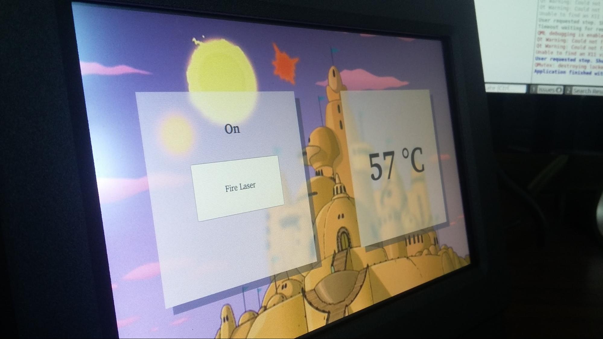
Neat, right? Clicking on the “Fire Laser” button will toggle the red LED in the back of the board and the CPU temperature is refreshed every second. Now, let’s discuss the project files and some of the code responsible:
Pro Tip: As mentioned in the “Yocto Startup Scripts” section of the TS-TPC-8390-4900 manual, you can make our new GUI application the default when booting up. Simply copy the compiled IMX6 binary to the board located in the build-HeatLaser-TS_IMX6-Debug/Release folder, and call it from within /usr/bin/mini-x-session, like this:
/usr/bin/HeatLaser &
exec matchbox-window-manager -use_titlebar no -use_cursor no
Backend Code
The backend code is made up of three main files: main.cpp, imx6.h, and imx6.cpp. We’ll discuss each in more detail below.
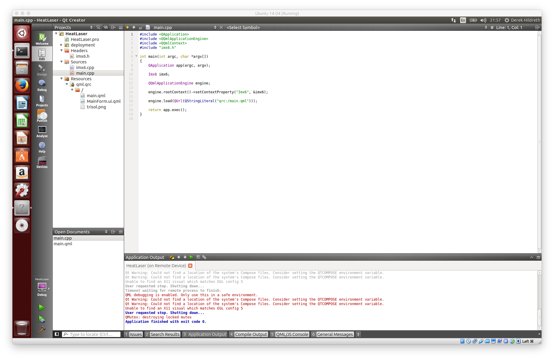
main.cpp
This file comes for free when you create a new Qt Quick Controls Application project. As mentioned before, you can learn more about it by watching this video on Qt Fundamentals. The only difference is we’re adding a contextual reference to our custom Imx6 class, which handles the board specific functions.
#include “imx6.h”
Imx6 imx6;
engine.rootContext()->setContextProperty("Imx6", &imx6);
We then load the QML Application Engine up with our frontend and execute our Qt Application.
engine.load(QUrl(QStringLiteral(“qrc:/main.qml”)));
return app.exec();
Let’s go ahead and move on into our TS-TPC-8390-4900 specific code.
imx6.h
This is a typical C++ header file with some Qt syntax sugar mixed in. You’ll notice the Q_OBJECT and Q_INVOKABLE macros added as well as a ‘signals’ and ‘slots’ mechanisms.
#include

class Imx6 : public QObject
{
    Q_OBJECT
public:
    explicit Imx6(QObject *parent = 0);
    ~Imx6();

    Q_INVOKABLE void getCurrentTemperature();
    Q_INVOKABLE void setRedLed(int isOn);
    Q_INVOKABLE int getRedLedStatus();
    Q_INVOKABLE void toggleRedLed();

signals:
    void temperatureUpdate(QString currentTemperature);
    void redLedStatusUpdate(QString currentRedLedStatus);

public slots:
};
The Q_OBJECT macro is described in the Qt documentation:
The moc [Meta-Object Compiler] tool reads a C++ header file. If it finds one or more class declarations that contain the Q_OBJECT macro, it produces a C++ source file containing the meta-object code for those classes. Among other things, meta-object code is required for the signals and slots mechanism, the run-time type information, and the dynamic property system.
So, the macro produces a C++ source file which contains code to implement the signals and slots mechanisms, among other things.
The Q_INVOKABLE macro is described in the Qt documentation:
Apply this macro to declarations of member functions to allow them to be invoked via the meta-object system.
Again, an important piece which generates code so that our methods can be called from our QML file.
The “signals” and “slots” method categories or mechanisms are summarized nicely in the Qt for Beginners wiki article:
Instead of having observable and observers, and registering them, Qt provides two high level concepts: signals and slots.
- A signal is a message that an object can send, most of the time to inform of a status change.
- A slot is a function that is used to respond to a signal.
We’ll use signals in our application in order to send our UI code status updates for the red LED and CPU temperature readings.
imx6.cpp
Like with any C++ source file, this is where our implementation code resides. If you start taking a look at the code, you should get some warm fuzzy feelings because it looks just like any other source file. There are a couple of interesting bits though. First of all, there are a couple of directives using Qt specific defines.
#if defined(Q_OS_LINUX) || (defined(Q_OS_UNIX) && !defined(Q_OS_OSX))
    ifile = "/sys/class/thermal/thermal_zone0/temp";
    ifstream temperatureFile ("/sys/class/thermal/thermal_zone0/temp");
    temperatureFile >> val;
    temperatureFile.close();
#elif defined(Q_OS_MAC) || defined(Q_OS_WIN) || defined(Q_OS_OSX)
    val = "54321";
#endif
Pro Tip: There’s a possible gotcha here that the author originally didn’t account for. It’s possible the temperature is in the single digits and not padded with a leading ‘0’ character or the temperature is negative with leading ‘-‘ character. The example code only expects double positive digits, so it’ll need to be improved upon in a production environment.
This isn’t anything too special. We’re just accounting for different development environments. If you recall, we were using a workflow which used both a Mac OSX machine and a Linux VM. In the code block above, we’re simply saying if we’re on Mac or Windows to just assign an arbitrary value to val. If we’re on Linux, then we’ll actually gather CPU temperature data as found in the file /sys/class/thermal/thermal_zone0/temp. This allows us to run the project from either environment.
The other interesting bit is this emit call. Remember our signals in the header file? This is how we ’emit’ those signals.
emit temperatureUpdate(buffer);
Here, we’re emitting a signal that the temperature has been updated, and we’re feeding it the temperature string. In our UI, any component listening to the ‘onTemperatureUpdate’ trigger will get this temperature string. We’ll take another look at this in the next section, but as for the rest of this C++ source file, suffice it to say the documentation is in the code and fairly self-explanatory. We have a functions to toggle the red LED on or off and another function to provide the LED status. It isn’t going to win any “sexiest code” or “best commented” awards, but it’s still a nice boost to get you going.
Frontend Design
Our front end code resides in main.qml. As mentioned before, this is a Qt Meta/Model Language file and resembles JSON in how it’s structured. It’s quite powerful, and we’re only skimming the tip of what it can do. If you’re interested in learning about how to develop a well-thought out application, take a look at the video Introducing Qt Quick Controls in Qt 5.1 where the presenter does a great job walking you through solid design principles. For now, forgive the uninspired structure and we’ll move onto talking about the details.
main.qml
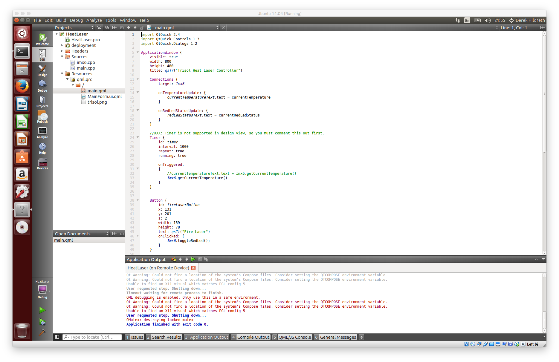
First off, you’ll notice everything is wrapped up within an ApplicationWindow element. Here, we’ve defined basic things like resolution and title.
ApplicationWindow {
    visible: true
    width: 800
    height: 480
    title: qsTr("Trisol Heat Laser Controller")
    ...
}
Within the ApplicationWindow, we have four UI elements: one button, two text fields, and a background image. You’ll also notice two other elements which are more like background workers: connections and timer. Let’s first take a closer look at the connections element.
Connections {
    target: Imx6

    onTemperatureUpdate: {
        currentTemperatureText.text = currentTemperature
    }

    onRedLedStatusUpdate: {
        redLedStatusText.text = currentRedLedStatus
    }
}
Taking a look at the target, you’ll notice it’s set to the same name as what we defined in the main.cpp file when setting the engine context property.
engine.rootContext()->setContextProperty("Imx6", &imx6);
Then, we have our signal connections, onTemperatureUpdate and onRedLedStatusUpdate, both of which are defined in our imx6.h file and emitted in our imx6.cpp file. The variables currentTemperature and currentRedLedStatus are defined in the imx6.h file where we declared the signal functions. These variables are then assigned to UI elements and their properties using a dot notation (ie. elementId.property = variable).
To clarify, when onTemperatureUpdate signal goes off, the UI text element with id currentTemperatureText will get it’s text element updated with the value in currentTemperature. This is responsible for displaying our current CPU temperature.
Text {
    id: currentTemperatureText
    x: 456
    y: 108
    width: 268
    height: 265
    color: "#292929"
    text: "-"
    z: 1
    horizontalAlignment: Text.AlignHCenter
    verticalAlignment: Text.AlignVCenter
    font.bold: true
    font.pixelSize: 72
}
The piece which actually fires off this signal is the Timer element.
Timer {
    id: timer
    interval: 1000
    repeat: true
    running: true

    onTriggered:
    {
        Imx6.getCurrentTemperature()
    }
}
Notice the timer is set to a repeating interval of 1 second and triggers a call to Imx6.getCurrentTemperature(). When that function runs, it emits the “temperatureUpdated” signal and the connection element then updates our text element with the new text. This doesn’t require any input from the user.
To control the red LED, we’re using a simple button that the user will press to turn on or off the LED.
Button {
    id: fireLaserButton
    x: 131
    y: 201
    z: 2
    width: 159
    height: 78
    text: qsTr("Fire Laser")
    onClicked: {
        Imx6.toggleRedLed();
    }
}
You can see that the button has some basic information associated with it: id, x,y,z coordinates, height and width, button text, and an action of “onClicked”. When we click the button, it’ll make a call to Imx6.toggleRedLed() and toggle the LED.
Other properties of the button were set by using the Qt Quick Designer. Clicking on the “Design” button in the left sidebar will take you there, but you’ll get a warning about unsupported features.
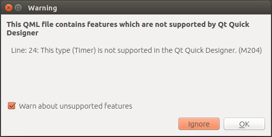
This is just saying that the Timer element type is not supported in the designer view, which is understandable. Simply ignore this message and you’ll be brought to a screen that looks like the screenshot below.
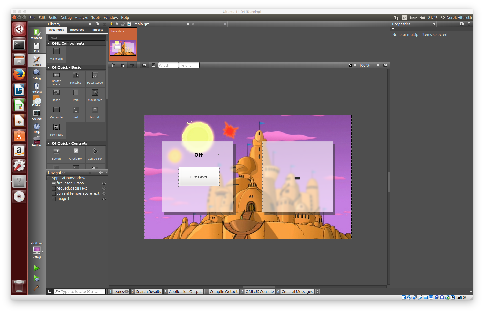
This is a nice tool for developing a UI quickly and acts like a WYSIWYG editor for UI design. You can drag and drop QML components to your canvas and then move them where you want. The coordinates will be updated in the main.qml source file. You’ll likely bounce back and forth between design view and code view for the main.qml file often.
We just scraped the surface, so you’re going to want to spend some time over at Qt Essentials — Qt Quick Edition getting to intimately know the Qt Quick framework to build and design spectacular user interfaces.
Finishing Up

In this guide, we dissected an example project file built specifically for the TS-TPC-8390-4900 in order to maintain a temperature sensitive facility on the planet Trisol (which really might exist). The project demonstrated how to read in data from a sensor and control a LED using a button, which is foundational in the world of HMI for SCADA applications. Resources for additional learning were provided along the way to help deepen your understanding of the Qt Quick Controls framework.
Are there any glaring omissions? Anything more you’d like to see? Please leave your thoughts and feedback in the comments below. Home
Thanks for the informative blog! Will we be seeing you at the Qt World Summit in San Francisco next week? It’s not too late to register. On behalf of The Qt Company, here’s a special discount code for you and your readers on a two or 3 day pass at 15% off: QtBlogger15off
http://www.qtworldsummit.com
Glad you found it informative! I hope it turns out to be a great resource for the Qt community looking at getting started in embedded touch panel systems.
Information are really nice and helpful.it helps other a lot.
Data acquisition system